The primary
advantage of the invention is that the oral surgeon may select the optimum position for dental implants using the three-dimensional
computer graphics model of the jawbone and tissue structure. Selection of the
drill hole positions using the
computer graphics model is transferred to a CNC device for the purposes of providing fixed
drill guide sockets in the template body for each one of the
drill hole positions or position selected using the
computer graphics model. While the model is three-dimensional, it may be convenient for the purposes of selecting the
drill hole axis to use a two-dimensional representation of the jawbone and tissue structure, the two-dimensional view being displayed with a user controlled slice angle. Preferably, the
dental surgeon will select the position for each implant drill hole, not only to position the implant in the optimum location within the jawbone, but also to result in a position of support which is suitable for supporting the
dentures. Therefore, it is preferred to display, in addition to the three-dimensional computer
graphics model of the jawbone and tissue structure, the patient's dentures in the proper
spatial relationship with respect to the jawbone and tissue structure. This requires imaging the patient's dentures or teeth, and possibly gum structure, in addition to the jawbone and tissue structure, in such a way that all images are referenced with respect to one another to be integrated into the same three-dimensional computer
graphics model.
is that the oral surgeon may select the optimum position for dental implants using the three-dimensional computer
graphics model of the jawbone and tissue structure. Selection of the drill hole positions using the computer graphics model is transferred to a CNC device for the purposes of providing fixed
drill guide sockets in the template body for each one of the drill hole positions or position selected using the computer graphics model. While the model is three-dimensional, it may be convenient for the purposes of selecting the drill hole axis to use a two-dimensional representation of the jawbone and tissue structure, the two-dimensional view being displayed with a user controlled slice angle. Preferably, the
dental surgeon will select the position for each implant drill hole, not only to position the implant in the optimum location within the jawbone, but also to result in a position of support which is suitable for supporting the dentures. Therefore, it is preferred to display, in addition to the three-dimensional computer graphics model of the jawbone and tissue structure, the patient's dentures in the proper
spatial relationship with respect to the jawbone and tissue structure. This requires imaging the patient's dentures or teeth, and possibly gum structure, in addition to the jawbone and tissue structure, in such a way that all images are referenced with respect to one another to be integrated into the same three-dimensional computer graphics model.
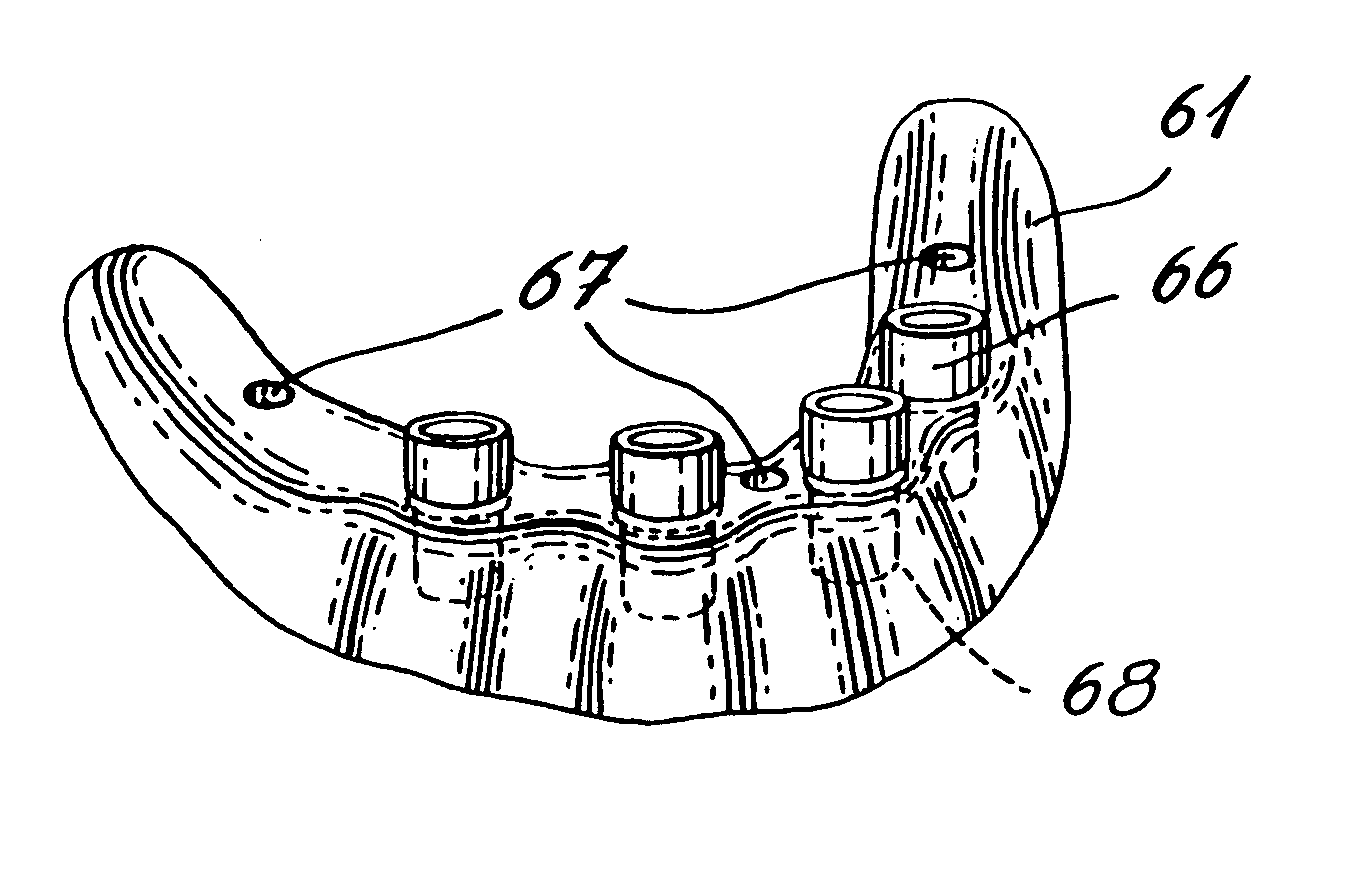
While it would be possible to prepare the drill template body and provide it with the
drill guide sockets using the CNC device, the drill template body is preferably molded on a
physical model of the gum surface into which model the CNC device has previously drilled the desired implant drill holes. The drill holes in the
physical model are used to build a mold for the drill guide sockets. This prevents the need to use the CNC device to produce fine details except for the precision drilling of the drill holes.
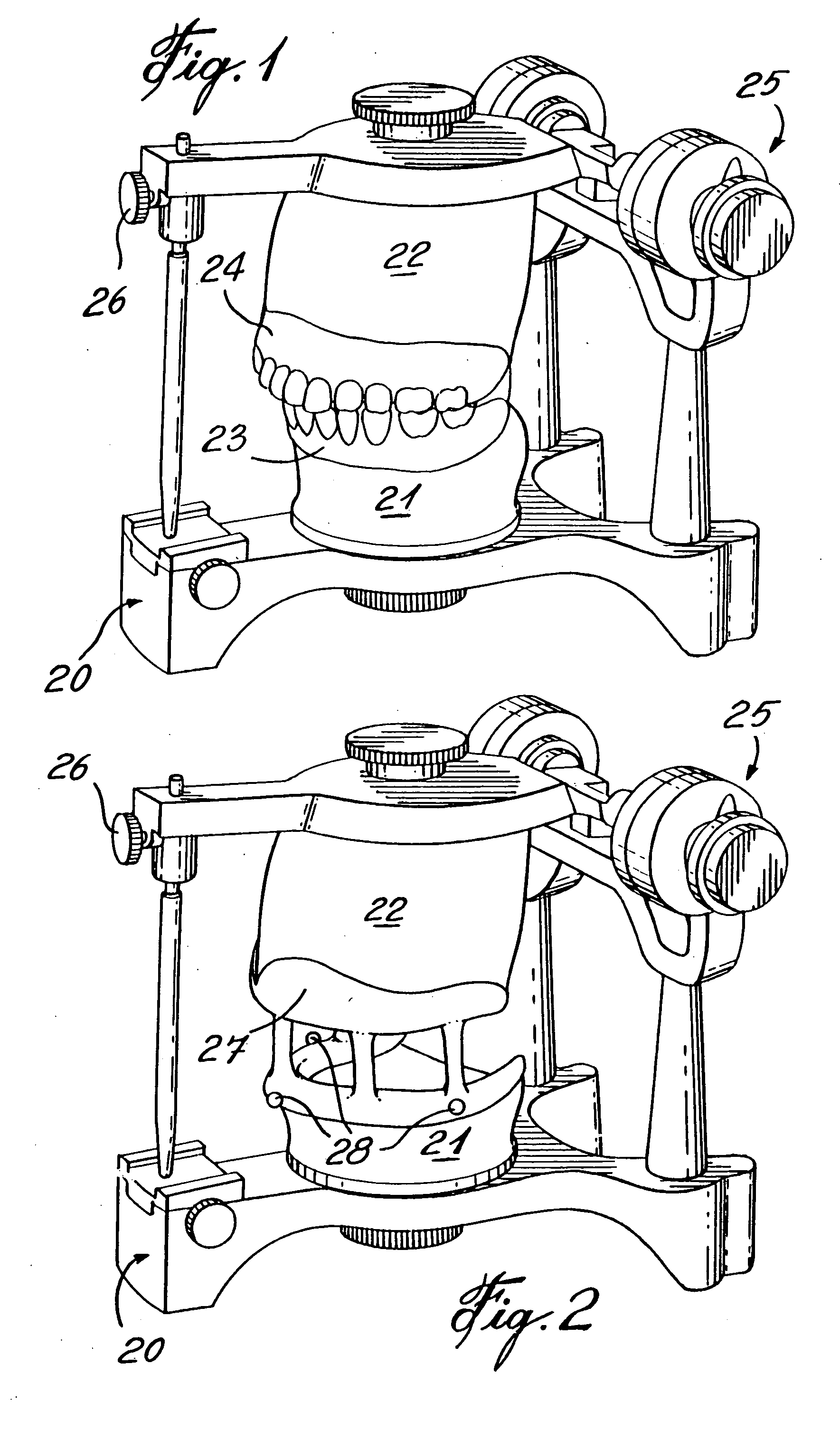
Imaging of the dentures or teeth to be placed over the gum surface and the imaging of the gum surface can be carried out by using
laser camera imaging techniques known in the art. These images are preferably obtained using a
physical model of the patient's gum surface, and the physical model is imaged in such a way that the images can be referenced accurately to the jawbone and tissue structure images.
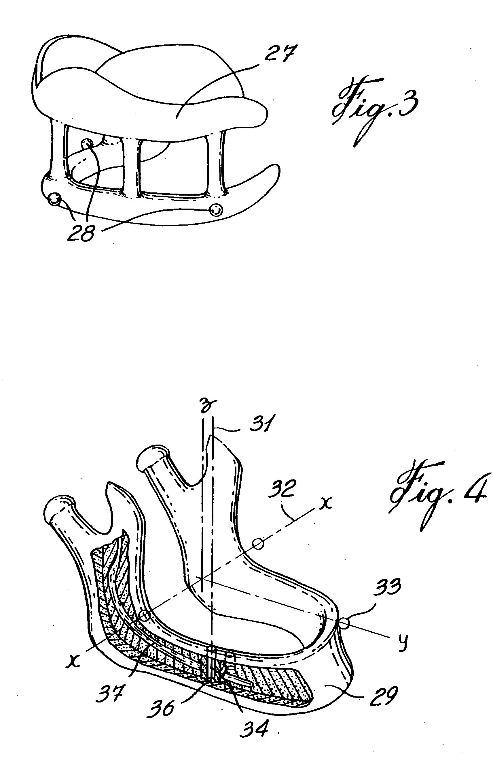
According to one method of manufacturing the dental implant superstructure, the actual dental implant position data is obtained by taking an imprint using transfers connected to the implants. Preferably, the imprint is taken using the same drill guide with the sockets of the drill guide being large enough to receive the transfers and surrounding imprint material. Preferably, the positions and orientations of the transfers are physically measured along with a reference to the drill guide which will permit the relative positions of the implants to be known with a reference to a standard
frame of reference. Using the standard
frame of reference, it is possible to generate a computer graphics model of the gum surface, dentures or teeth and dental implants which allows the dental surgeon or
technician to select the best shape for the overlying bridge of the superstructure.
According to a further general aspect of the present invention, the implant drill hole positions selected using the computer graphics model can also be used to make the superstructure. By so using the planned implant positions, instead of taking an imprint of the implants inserted in the patient's jawbone to precisely determine their actual locations in relation to the jawbone, the superstructure can be made prior to the
surgical operation, i.e. prior to the
insertion of the implants into the patient's jawbone. This advantageously provides for the installation of the implants and the superstructure in a single
surgical operation. This novel approach of creating a superstructure on the basis of the virtual positions of the dental implants selected using the three-dimensional computer graphic model of the jawbone and the dental prosthesis has the following advantages for the surgeon: no need for taking imprints of the implants to determine their positions in the jawbone; no need for a second surgical procedure to
expose the head of the implants; improved stability of the implants, as they are immediately interconnected to each other by the superstructure; improved protection of the implants, since they are better stabilized; less sessions with a patient, thus, higher profitability;

