Insertable sensor assembly having a coupled inductor communicative system

Inactive Publication Date: 2005-02-17
ISENSE CORP
View PDF14 Cites 186 Cited by
  • Summary
  • Abstract
  • Description
  • Claims
  • Application Information

AI Technical Summary

Benefits of technology

[0007] In a second separate aspect, the present invention is an improvement to a biological sensing system that includes an in vivo portion, adapted to reside inside a patient, an ex vivo portion physically attached to the in vivo portion and having an antenna and an electronic monitoring unit that is physically separate from, but in wireless comm

Problems solved by technology

One problem encountered in the design of the ex vivo portion is the reduction of ex vivo portion s

Method used


Image

  • Insertable sensor assembly having a coupled inductor communicative system
  • Insertable sensor assembly having a coupled inductor communicative system

Examples


Embodiment Construction

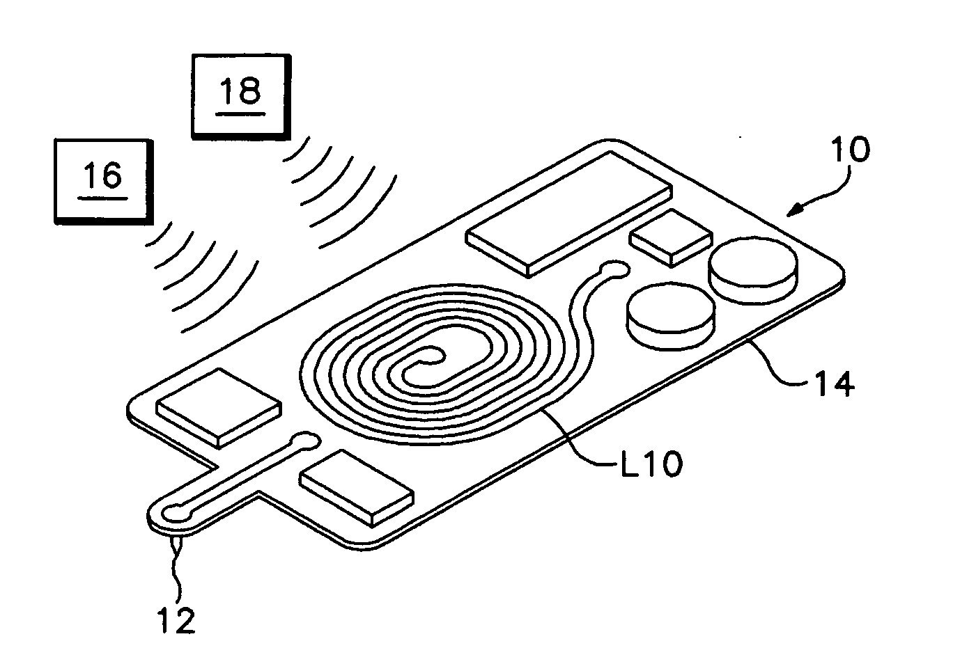
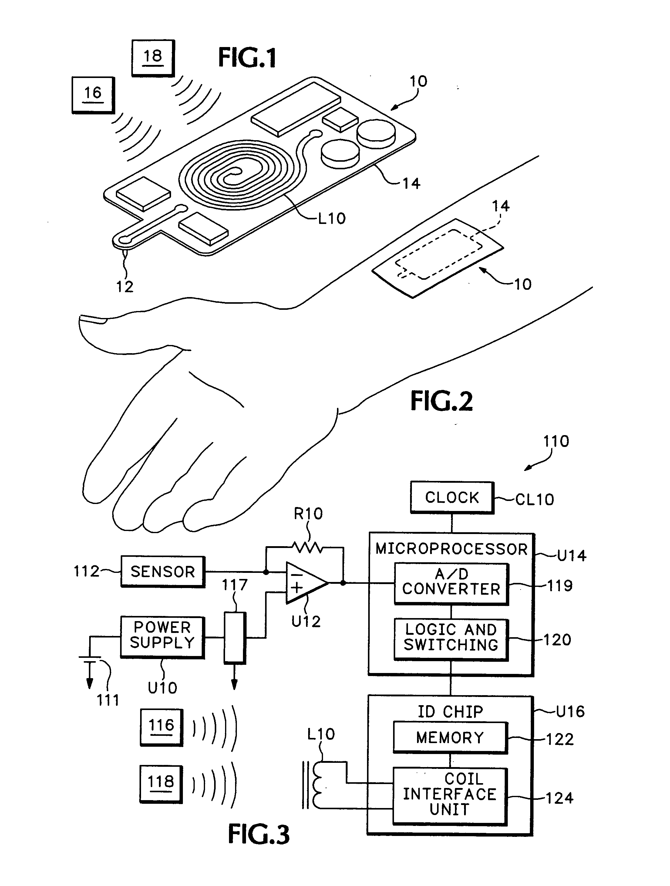
[0012] As described in the Background section, and as shown in FIGS. 1 and 2, in a preferred embodiment a glucose sensing and reporting assembly 10 includes an in vivo glucose sensing element 12 and an ex vivo portion 14, which transmits the data from sensing element 12 to an electronic monitoring unit 16. Together, elements 12 and 14 may be considered a glucose or analyte sensing patch.

[0013] In vivo portion 12 may be as described in U.S. Pat. No. 5,165,407. This portion must have a voltage placed across it of 0.65 VDC and produces a sensor current that is generally proportional to the concentration of glucose in body tissue. A typical value for the sensor current is about 5-10 nanoAmps.

[0014] In FIG. 3, elements that could be the same as an element in FIG. 1 or 2, are labeled with the same reference number as in FIG. 1 or 2, plus 100. Referring to FIG. 3, ex vivo portion includes a 3 VDC battery 111 that drives a power supply U10. The 2.048 VDC output of power supply U10 is fed ...


PUM


Abstract

A sensing system for determining the concentration of an analyte inside an animal body. The system includes an in vivo portion that is adapted to reside inside the animal body and that includes a sensing element that produces a sensing signal. In addition, a wearable ex vivo portion is physically attached to the in vivo portion. The ex vivo portion includes a first inductor that is adapted to receive a varying electro-magnetic signal and that has a pair of terminals. A variable load assembly presents a load across the pair of terminals and varies the load in response to the sensing signal. Also, an electronic monitoring unit is physically separate from the ex vivo portion and includes a second inductor, which is magnetically coupled to the first inductor and is adapted to transmit a varying electro-magnetic signal and to detect changes in load across the terminals of the first inductor.

Description

BACKGROUND OF THE INVENTION [0001] Implanted medical devices frequently include a wire coil that is used to receive an electromagnetic wave broadcast from outside the body. Often the transmitted signal is used for information content and to power the embedded device. Referring to FIGS. 1 and 2, which show a system under development that includes a few prior art features that will be discussed here, a system 10 that is currently being developed for the sensing of glucose relies on a very thin “wire” type sensing element 12 that is inserted into the patient's subcutaneous tissue for a few days to a few weeks, depending on the particularities of the implementation. The system 10 also includes an ex vivo portion 14 that is physically attached to the sensing element 12, but resides outside the body and may be adhered to the skin. [0002] Another portion, referred to as the electronics monitoring unit 16 or “EMU,” is in wireless communication with the ex vivo portion 14. The EMU 16 is typi...

Claims


Application Information

Patent Timeline
IPC IPC(8): A61B5/00
CPCA61B5/0031A61B2560/0219A61B5/14865A61B5/14532
Inventor SILASKI, GRAYSONBIRCK, JONATHAN D.
Owner ISENSE CORP
Why Eureka
Try Eureka