
Digitally controlled luminaire system

a digital control and luminaire technology, applied in the field of luminaires, can solve the problems of undesired effects on the spectral power distribution of the resultant output light, the complexity of the compensation effect, and the number of parameters that affect the luminaire in a complex way

Inactive Publication Date: 2008-01-15
SIGNIFY HLDG BV
View PDF11 Cites 232 Cited by
  • Summary
  • Abstract
  • Description
  • Claims
  • Application Information

AI Technical Summary

Benefits of technology

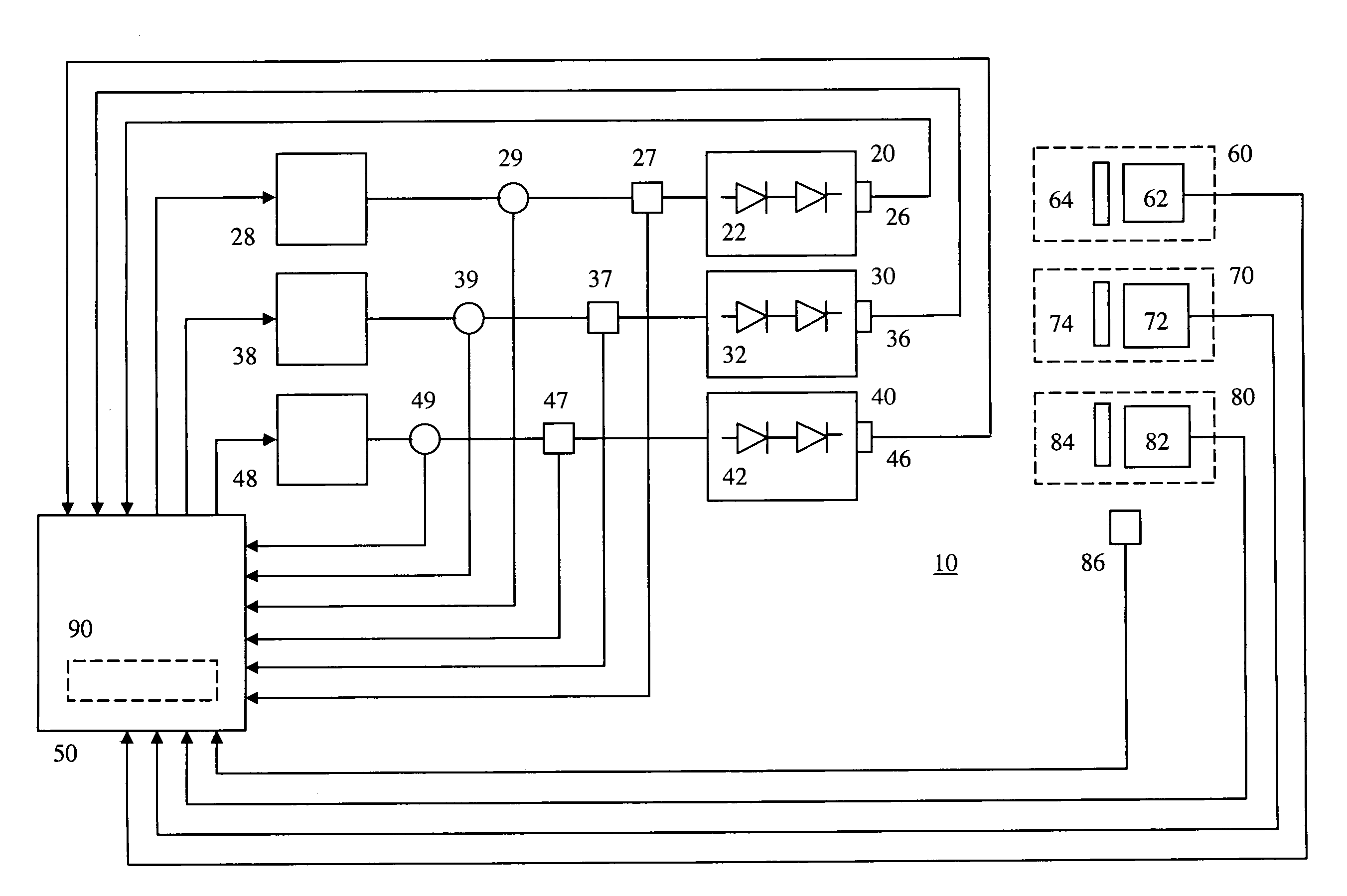
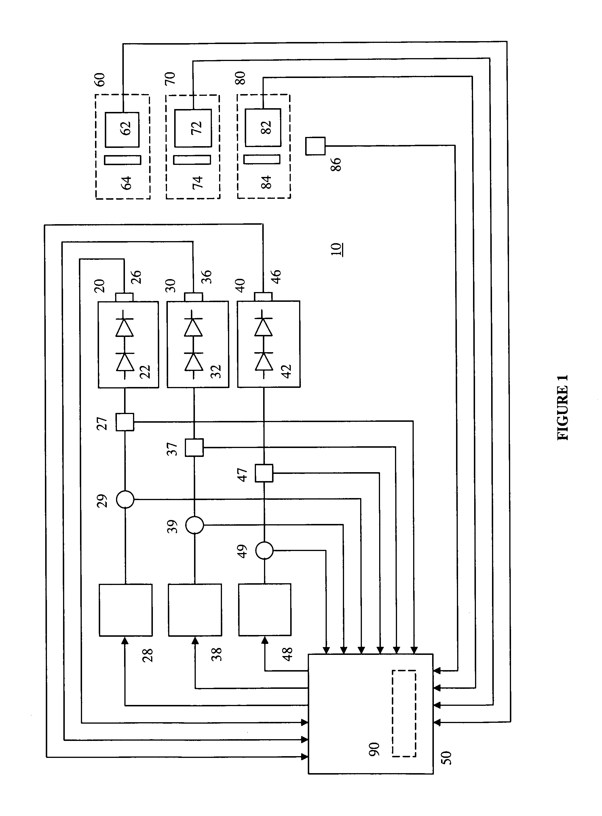
The present invention provides a digitally controlled luminaire system that can generate light with a desired color and brightness. The system includes an array of light-emitting elements, a current driver system, an optical sensor system, a heat sensing system, and a controller. The controller analyzes the optical signals from the sensor system and the temperature signals from the heat sensing system to determine the desired color and brightness of the light. The controller then adjusts the current driver system to achieve the desired color and brightness. The system can be connected to a power source and is adaptable for different lighting needs.

Problems solved by technology

In spite of their success, LED-based luminaires can be affected by a number of parameters in a complex way.
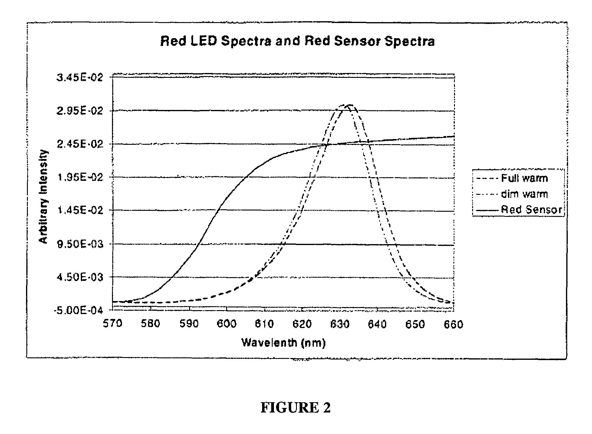
Chromaticity and luminous flux output of LEDs can greatly depend on junction temperature and drive current as well as device aging effects that result in efficacy degradation over time, which can have undesirable effects on the CCT and more generally the chromaticity of the emitted light.
However, changes in the average forward current can affect the junction temperature of the LED, which can alter the spectral power distribution and in consequence the CCT or chromaticity and luminous flux of the light emitted by the LED.
The compensation of this effect can become complex when various coloured LEDs are used to generate mixed light of a desired chromaticity.
LED junction temperature variations can also cause undesired effects on the spectral power distribution of the resultant output light.
Variations in junction temperature not only can reduce the luminous flux output, but can also cause undesirable variations in the CCT of the mixed light.
Overheating can also reduce the life span of LEDs.
While the Nishimura reference provides an effective way to achieve control of the spectral power distribution of the output light with any desired colour property, it does not consider maintaining colour stability over the life of the LEDs and at different operating conditions, including dimming.
The Muthu reference however does not provide a solution for alleviating the discrepancies in the colour temperature of the desired light that are caused by the shifting of peak wavelength of the LEDs over time.
In addition, the calculations required for the mathematical transformation make it difficult to implement a feedback control system with a response time that is fast enough to avoid visual flicker during dimming operations, for example.
The Muthu et al. reference however does not account for shifting of the peak wavelength of the LEDs due to temperature, dimming, or age of the components.
In addition, the calculations required for the mathematical transformation between the two sets of tristimulus values makes it difficult to implement a feedback control system with a response time that is fast enough to avoid visual flicker during dimming operations, for example.
However, the method disclosed by Schuurmans does not account for shifting of the peak wavelength of the LEDs due to temperature, dimming, or age of the components.
Muthu et al. however, fail to consider the junction temperature during dimming of the LEDs.
Muthu et al. also fail to consider the effect of peak wavelength shift and photodiode inaccuracies on the white light produced.
A drawback of this procedure as disclosed by Muthu et al. is the excessive amount of thermal stress imposed on the LEDs during ON and OFF cycles at low frequencies.

Method used


Image

  • Digitally controlled luminaire system
  • Digitally controlled luminaire system
  • Digitally controlled luminaire system

Examples


Embodiment Construction

Definitions

[0024]The term “light-emitting element” is used to define any device that emits radiation in any region or combination of regions of the electromagnetic spectrum for example, the visible region, infrared and / or ultraviolet region, when activated by applying a potential difference across it or passing a current through it, for example. Therefore a light-emitting element can have monochromatic, quasimonochromatic, polychromatic or broadband spectral emission characteristics. Examples of light-emitting elements include semiconductor, organic, or polymer / polymeric light-emitting diodes, blue or UV pumped phosphor coated light-emitting diodes, optically pumped nanocrystal light-emitting diodes or any other similar light-emitting devices as would be readily understood by a worker skilled in the art. Furthermore, the term light-emitting element is used to define the specific device that emits the radiation, for example a LED die, and can equally be used to define a combination o...


PUM


Abstract

The present invention provides a luminaire system capable of generating light of a desired chromaticity and luminous flux output during continuous operation with varying ambient operating temperature. The luminaire system can be further capable of maintaining a desired correlated colour temperature during dimming of the luminaire. The luminaire system comprises one or more arrays of light-emitting elements for generating light with a current driver system coupled thereto for selectively supplying electrical drive current to each of the arrays, wherein the current driver system is responsive to drive signals received from a controller. The luminaire system further comprises an optical sensor system for generating optical signals representative of chromaticity and luminous flux output of the light. A heat sensing system is operatively coupled to the one or more arrays for generating signals representative of the junction temperatures of arrays of light-emitting elements during operation. The luminaire system further comprises a controller that is operatively connected to the current driver system, the optical sensor system and the heat sensing system for receiving the signals generated by each of these systems and is configured to generate one or more drive signals for transmission to the current driver system in response to the optical signals and thermal signals received from the optical system and the heat sensing system, respectively, thereby enabling a desired level of control of the output light.

Description

[0001]This application claims priority from now expired U.S. Provisional Patent Application No. 60 / 709,217 filed Aug. 17, 2005.FIELD OF THE INVENTION[0002]The present invention pertains to luminaires, and particularly to a luminaire system capable of maintaining desired lighting conditions, for example constant colour temperature, during operation.BACKGROUND[0003]Recent technological advancements in light-emitting diode (LED) design have been a boon to the lighting industry. With their high overall luminous efficacy and flexibility for achieving various light patterns, LED-based luminaires are increasingly being used in signage, advertising, display lighting, and backlit lighting applications. LED-based luminaires are also replacing the traditional incandescent or fluorescent lighting fixtures to become the mainstream lighting architecture.[0004]Due to its natural lighting characteristics, white light is the preferred choice for lighting. An important consideration for LED-based lum...

Claims


Application Information

Patent Timeline
Patent Type & Authority Patents(United States)
IPC IPC(8): G05F1/00H05B44/00
CPCH05B33/086H05B33/0863H05B33/0872H05B33/0869Y10S362/80H05B45/22H05B45/28
Inventor JUNGWIRTH, PAULROBINSON, SHANE P.SPEIER, INGOASHDOWN, IAN
Owner SIGNIFY HLDG BV
Learn More