Electrode array for use in medical stimulation and methods thereof

Inactive Publication Date: 2005-02-17
CASE WESTERN RESERVE UNIV
View PDF27 Cites 298 Cited by
  • Summary
  • Abstract
  • Description
  • Claims
  • Application Information

AI Technical Summary

Benefits of technology

[0021] The present invention provides an electrode array for use in medical stimulation, such as cardiac or neural stimulation, which reduces impedance and thus power consumption and thereby increases battery life. The present invention is able to reduce impedance by simply increasing the perimeter or edges of conductive sections of the electrode.
[0022] With t

Problems solved by technology

Although these medical devices are quite effective, their usefulness is limited by the life span of the batteries used to power them.
Although some of these new m

Method used


Image

  • Electrode array for use in medical stimulation and methods thereof
  • Electrode array for use in medical stimulation and methods thereof
  • Electrode array for use in medical stimulation and methods thereof

Examples


Example

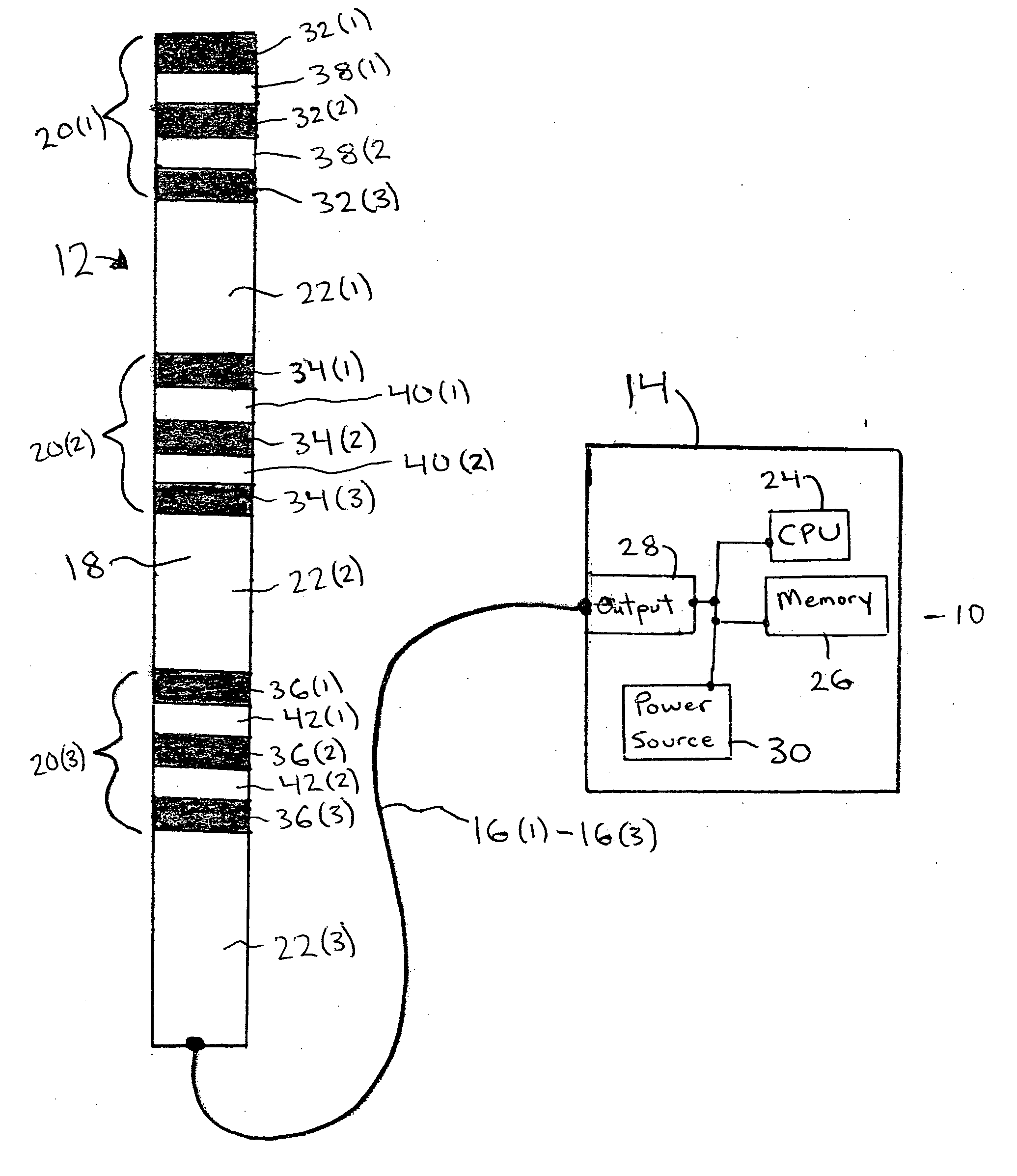
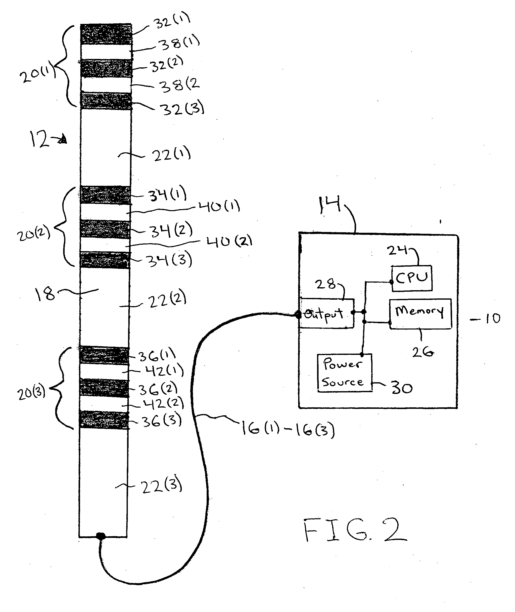
[0044] A medical device 10 with an electrode array 12 in accordance with embodiments of the present invention is illustrated in FIG. 2. The medical device 10 includes the electrode array 12 with an array body 18 and electrodes 20(1)-20(3), a pulse generator 14, and leads 16(1)-16(3), although the medical device 10 may comprise other types, numbers, and combinations of components, such as one or more of electrodes 20(4)-20(13). The present invention provides an electrode for use in an electrode array which reduces impedance and thus power consumption and thereby increases battery life by increasing the outer perimeter or edges of the electrodes in the electrode array.

[0045] Referring more specifically to FIG. 2, the electrode array 12 includes an array body 18 with electrodes 20(1)-20(3) and insulating regions 22(1)-22(3), although the electrode array 12 may comprise other types, numbers, and combinations of electrodes, insulating regions, and other components. Electrodes 20(1)-20(3...


PUM


Abstract

An electrode array for use in medical stimulation includes one or more electrodes along an array body and one or more leads. Each of the electrodes has one or more conductive sections and each of the conductive sections has an outer surface which is substantially exposed from the array body for coupling to tissue. At least one of the electrodes has at least one of: adjacent pairs of the conductive sections separated by an insulating section; the conductive section having at least one portion which is spaced in from other portions of the conductive section and which substantially extends all the way around or all along a length of the conductive section; at least one substantially non-planar end; and a substantially planar shape with a substantially non-linear outer edge. Each of the electrodes has at least one of the leads coupled to each of the conductive sections of the electrode.

Description

[0001] This invention was made with Government support under Grant No. R01 NS40894, 9 / 30 / 00-9 / 30 / 05, awarded by the National Institutes of Health. The Government has certain rights in the inventions.FIELD OF THE INVENTION [0002] This invention relates generally to electrodes and, more particularly to an electrode array for use in medical stimulation, such as cardiac or neural stimulation. BACKGROUND OF THE INVENTION [0003] A variety of different types of medical devices, such as cardiac pacemakers, defibrillators, and neural stimulators, operate on battery power. Although these medical devices are quite effective, their usefulness is limited by the life span of the batteries used to power them. One of the largest drains of power from these batteries is at the interface between an electrode in the medical device and tissue. [0004] A circuit diagram illustrating the power drain in a medical device is illustrated in FIG. 1. A pair of leads represented by Rleads are coupled between a cu...

Claims


Application Information

Patent Timeline
IPC IPC(8): A61N1/05
CPCA61N1/05A61N1/0553A61N1/0551
Inventor GRILL, WARREN M.
Owner CASE WESTERN RESERVE UNIV
Why Eureka
Try Eureka