Variable speed pyrolytic waste treatment system

Inactive Publication Date: 2005-02-24
INT ENVIRONMENTAL SOLUTIONS
View PDF11 Cites 9 Cited by
  • Summary
  • Abstract
  • Description
  • Claims
  • Application Information

AI Technical Summary

Problems solved by technology

Unlike incineration, pyrolysis is the destructive decomposition of waste materials using indirect heat in the absence of oxygen.
Burning wastes through incineration with direct flame in the presence of oxygen can be explosive,

Method used


Image

  • Variable speed pyrolytic waste treatment system
  • Variable speed pyrolytic waste treatment system

Examples


Embodiment Construction

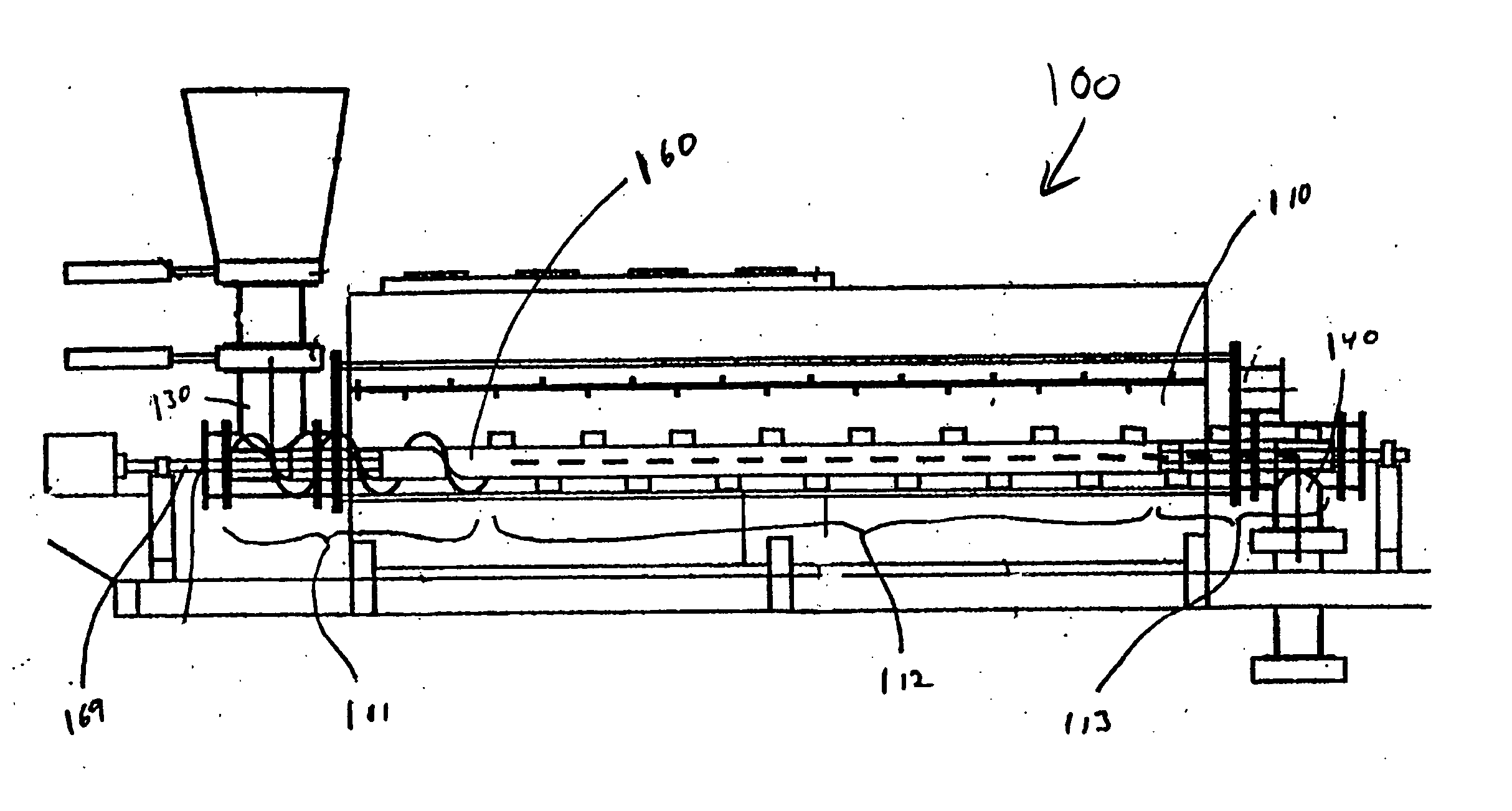
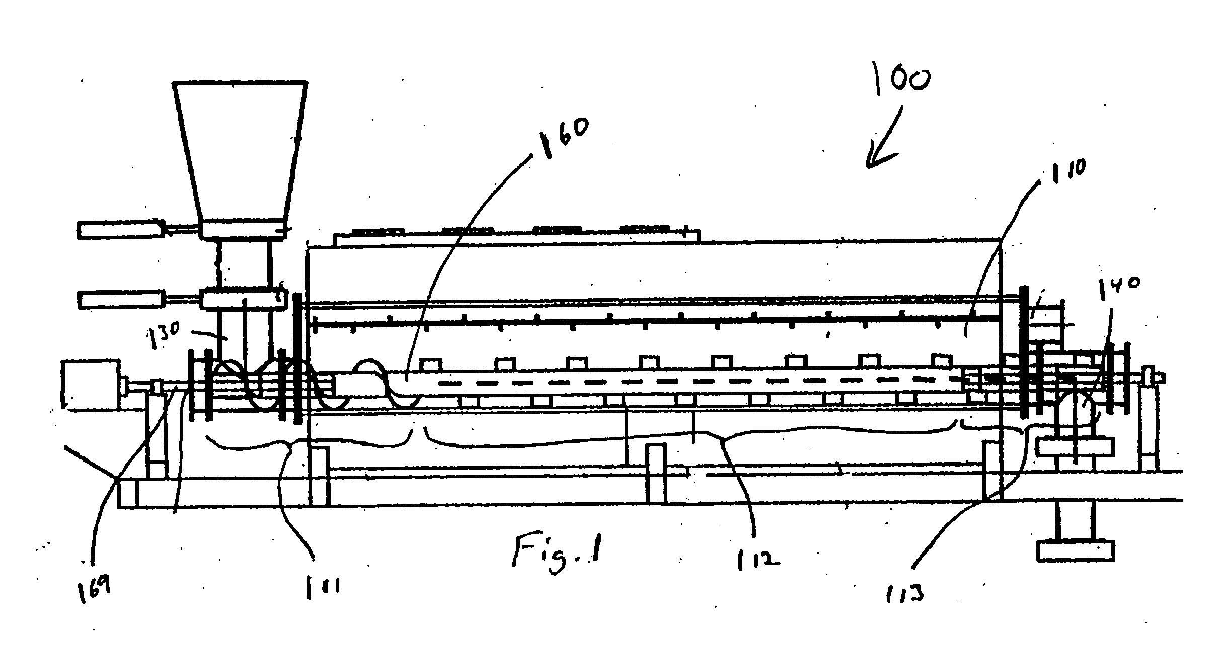
[0010] In FIG. 1, a pyrolytic waste treatment system 100 generally comprises a pyrolytic chamber 910 and a waste movement mechanism 960.

[0011] It is contemplated that it would be beneficial to vary the rate of movement of material through a pyrolysis chamber. In particular, material might move at a slower rate when it first enters the chamber and move at a faster rate after it has been heated and as is moved toward the chamber exit. It is contemplated that the use of paddles or a screw in which the pitch of the paddles or the screw threads varies from one end of the chamber to the other would prove beneficial. It should be recognized that other methods and devices may be used to move material through the chamber including, for example, using gravity, magnetism, and forced air. With regard to using magnetism, it is further contemplated that a product could be statically charged within a magnetic field. Other methods and devices are also contemplated so long as they move the product ...


PUM


Abstract

The inventive subject matter is directed toward a pyrolytic waste treatment system comprising a pyrolysis chamber and a movement mechanism adapted to move waste through the pyrolysis chamber at different speeds along the length of the pyrolysis chamber.

Description

[0001] This application claims the benefit of U.S. provisional application No. 60 / 497397 filed on 21 Aug. 2003 incorporated herein by reference in its entirety.FIELD OF THE INVENTION [0002] The field of the invention is pyrolytic waste treatment. BACKGROUND OF THE INVENTION [0003] Pyrolysis is a known method for treatment of waste. Examples of pyrolytic waste treatment systems can be found in U.S. Pat. Nos. 4,759,300, 5,653,183, 5,868,085, and 6,619,214. Unlike incineration, pyrolysis is the destructive decomposition of waste materials using indirect heat in the absence of oxygen. Burning wastes through incineration with direct flame in the presence of oxygen can be explosive, causing turbulence in the burning chamber, which fosters a recombination of released gases. Waste destruction in an oxygen-rich atmosphere makes conversion far less complete, is highly inefficient and creates harmful substances. [0004] In contrast, the pyrolytic process employs high temperature in, most desira...

Claims


Application Information

Patent Timeline
IPC IPC(8): C10BF23GF23G5/12F23G7/04F23J1/00F23K3/00F23M5/02
CPCC10B47/28C10B47/44C10B53/00F23G5/0273Y02E20/12F23G5/46F23G2201/303F23G2206/10F23G5/16Y02P20/129F23G7/04F23M5/02F23G5/12
Inventor COLE, CAMERONTORRES, RAUL DE LACOLE, TOBY L.WATTS, DAN
Owner INT ENVIRONMENTAL SOLUTIONS
Why Eureka
Try Eureka