Eureka AIR delivers breakthrough ideas for toughest innovation challenges, trusted by R&D personnel around the world.

Spin coating apparatus and coated substrate manufactured using the same

a technology of coating apparatus and coated substrate, which is applied in the direction of coating, instruments, data recording, etc., can solve the problems of inability to obtain uniform coating layer, inability to uniformly coat the entire substrate, and worsen ski-jumping

Inactive Publication Date: 2005-02-24
LG CHEM LTD
View PDF5 Cites 19 Cited by
  • Summary
  • Abstract
  • Description
  • Claims
  • Application Information

AI Technical Summary

Benefits of technology

[0012] The present invention provides a spin coating apparatus which can prevent an occurrence of a ski-jump.

Problems solved by technology

Due to the ski-jump, the entire substrate cannot be uniformly coated.
As the viscosity of the coating solution is increased, the ski-jump becomes worse.
At this time, a uniform coating layer cannot be obtained due to a formation of ski-jump.
Thus, such an optical disc does not satisfy the above-mentioned specification.
However, since this method includes additionally the cutting operation in the manufacturing process of the optical disc, manufacturing costs are increased and it takes a long time to manufacture the optical disc.
The manufacturing efficiency is degraded and the substrate may be broken, cracked and bent in the operation of cutting the bump.
In this case, however, it is difficult to extract the optical disc from the housing after the spin coating.
Also, the resin flows into a gap between the substrate and the housing, thereby contaminating a rear side of the optical disc.
In the repetitive coatings, the coating solution stays inside a jig and is not drained, causing serious contamination of the optical disc.
Although the size of the ski-jump is reduced compared to conventional spin coating methods, it is still difficult to obtain a uniform resin layer up to a radius of 58.5 mm, and the ski-jump is about 20 μm.
In the operation of implanting the impurities or forming the thin film layer, it is difficult to thickly form the photoresist layer to a thickness of tens of μm.
Since in this method, each of the coating process and the hardening must be performed twice, the manufacturing process is complicated and it takes a long time to manufacture the photoresist layer.
Also, wastewater is generated due to the thinner used to remove the edge bead of the first photoresist layer, thus increasing manufacturing costs for processing the wastewater.
The periphery of the silicon wafer comes into contact with other elements, causing a crack.
When the crack occurs, a large amount of foreign material occurs, thus reducing productivity.
This bump is a cause of foreign material such as the convex portion.
When the acoustic matching layer is formed by the spin coating method, the viscosity of the resin must be very high, such that a thickness unstable portion (ski-jump) occurs at the edge of the acoustic matching layer.
In this method, since the UV light is irradiated from a spin coater, an UV curable resin remaining at the spin coater is hardened when spin coating, making it difficult to remove the remaining resin.
Also, since this method requires the operation of cutting the thickness unstable portion, the productivity is degraded.

Method used


Image

  • Spin coating apparatus and coated substrate manufactured using the same
  • Spin coating apparatus and coated substrate manufactured using the same
  • Spin coating apparatus and coated substrate manufactured using the same

Examples


example 1

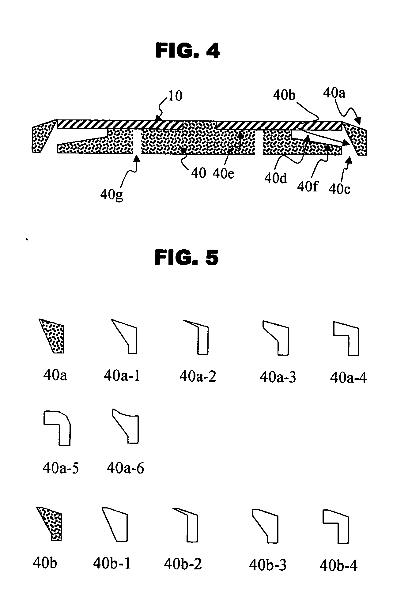
[0040] Referring to FIG. 4, the height of the inner portion of the upper surface 40b of the ring-shaped member was equal to that of the substrate, and the upper surface 40b of the ring-shaped member was inclined outwards with an angle of 15° and the inner surface Of the ring-shaped member was inclined outwards with an angle of 45°. The diameter of a surface of the supporter contacting the substrate 10 was 80 mm. The ring-shaped member and the supporter were formed of aluminum. A polycarbonate (PC) having a total thickness of 1.1 mm, an outer diameter of 120 mm and an inner diameter (diameter of a central hole) of 15 mm was injection molded. Then, the substrate 10 was manufactured by forming a four-layer structure of Ag alloy / ZnS—SiO2 / SbGeTe / ZnS—SiO2 with a sputtering process. Then, a cover layer with a thickness of 100μm was formed by spin coating EB 8402 (made by SK UCB) and Irgacure 184 (made by Ciba SC), 651 (made by Ciba SC), and UV curable resin having methylethylketone using t...

example 2

[0041] The substrate of the present example was manufactured in the same manner as in example 1, except that the cover layer was 75 μm thick. Coating thicknesses according to radii of the substrate are shown in Table 1 below.

example 3

[0042] The substrate of the present example was manufactured in the same manner as in example 1, except that the cover layer was 50 μm thick. Coating thicknesses according to radii of the substrate are shown in Table 1 below.


PUM


Abstract

A spin coating apparatus is provided. The spin coating apparatus includes a ring-shaped or polygonal member. An upper portion of the ring-shaped or polygonal member has an inclined portion extending downward and outward, and an inner portion of the inclined portion is adjacent to or in contact with an outer edge of a substrate. An inner side surface of the ring-shaped or polygonal member is inclined downward and outward. When a surface of the substrate is coated with a coating solution using the spin coating apparatus, a ski-jump phenomenon occurring at an outer edge of the substrate can be reduced and contamination of the substrate due to the coating solution can be prevented.

Description

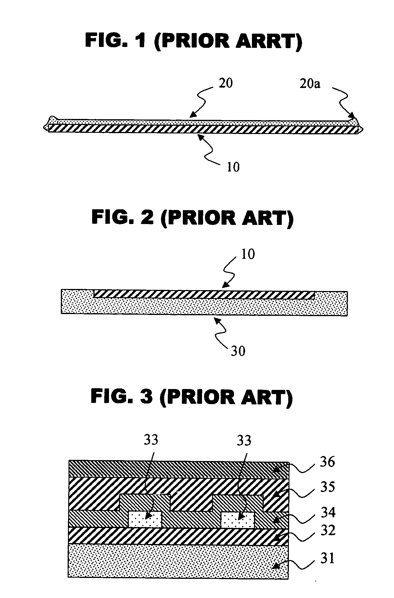
BACKGROUND OF THE INVENTION [0001] This application claims the priorities of Korean Patent Application No. 2003-0058133, filed on Aug. 22, 2003, and Korean Patent Application No. 2004-0065148, filed on Aug. 18, 2004, in the Korean Intellectual Property Office, the disclosures of which are incorporated herein in its entirety by reference. [0002] 1. Field of the Invention [0003] The present invention relates to a spin coating apparatus, and more particularly, to a spin coating apparatus capable of reducing ski-jump phenomenon (also referred to as a bump, a convex portion, an upheaval, a protrusion, a bead, and so on) occurring at an outer edge of a substrate when spin-coating with a ring-shaped or polygonal member and a coated substrate manufactured using the same. [0004] 2. Description of the Related Art [0005]FIG. 1 is a side view of coating solution spin-coated on a substrate using a conventional method. In said method a liquid coating solution is dropped on the central portion of ...

Claims


Application Information

Patent Timeline
IPC IPC(8): G11B7/26H01L21/00H01L21/687
CPCG11B7/266H01L21/68757H01L21/6715
Inventor KANG, TAE SIKHAN, MI YOUNGLEE, SEONGKEUNJANG, SUNG HOONHONG, YOUNGJUN
Owner LG CHEM LTD
Why Eureka
Eureka Blog
Learn More