Powered clamp application tool

a clamping tool and power supply technology, applied in the field of band application and cutting machine, can solve the problems of inability to bench mount the unit for production runs, limited use of bands, and high cost of custom clamping

Inactive Publication Date: 2005-02-24
ILLINOIS TOOL WORKS INC
View PDF28 Cites 2 Cited by
  • Summary
  • Abstract
  • Description
  • Claims
  • Application Information

AI Technical Summary

Benefits of technology

[0021] This tool can be operated portably with a small battery power supply. This allows the operator to go into the field and apply hose clamps without having compressed air or AC electricity available. The tool is of light enough weight to allow bringing the tool to the job as opposed to the present system which demands that the job be brought to the tool. This tool can also be operated as a bench tool with foot operated control, either by

Problems solved by technology

Problems with the Band-It™ units include the limitation of use with Band-It's expensive custom clamps, only available in a ¾″ width.
Another problem with the Band-It™ units is the requirement to manuall

Method used


Image

  • Powered clamp application tool
  • Powered clamp application tool
  • Powered clamp application tool

Examples


Embodiment Construction

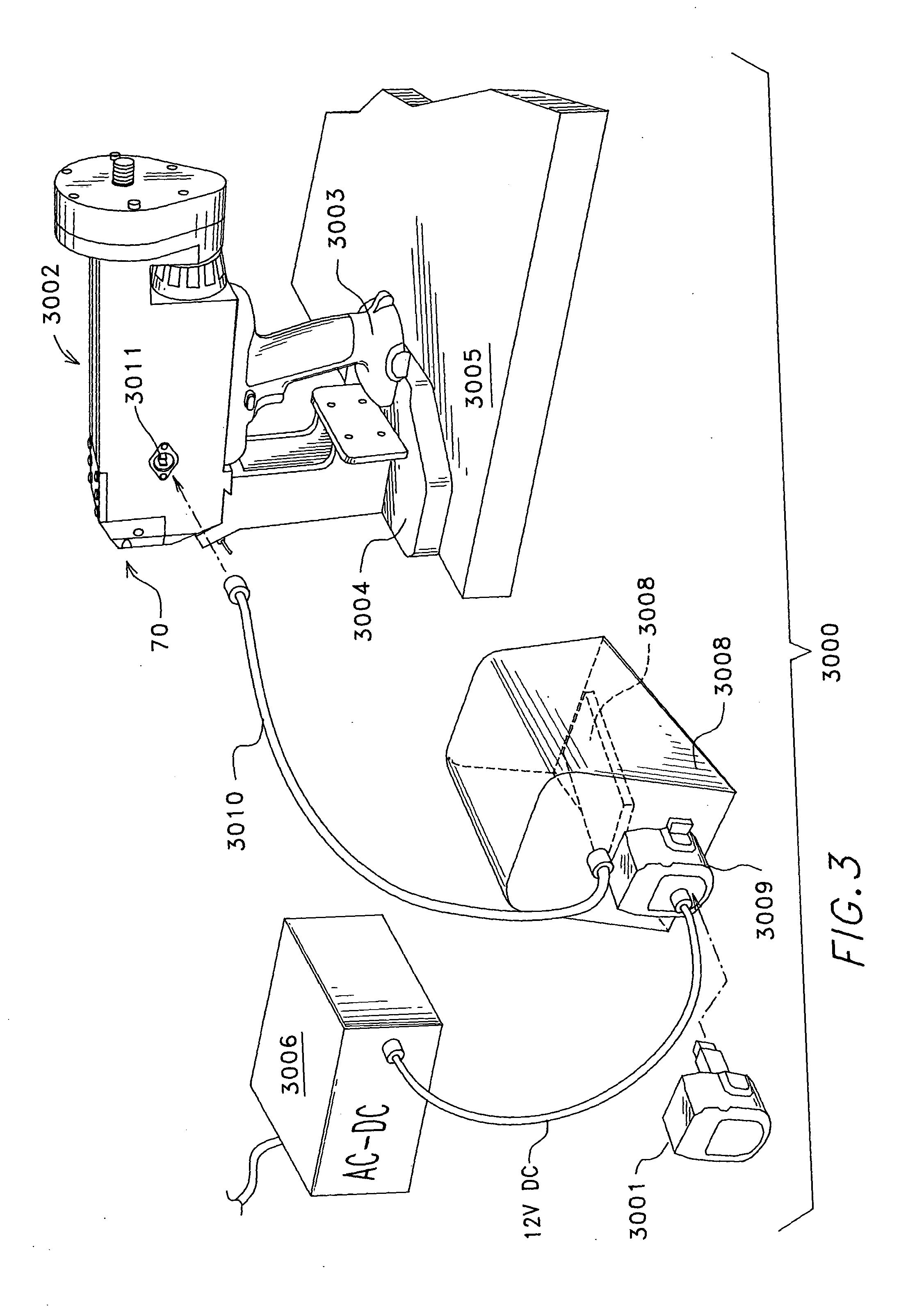
[0063] Referring next to FIG. 3 a universal clamp application system 3000 is shown. For portable use a battery pack 3001, is plugged into the application module 3002 at handle 3003. The application module is detached from the bench mount 3004 and fully operational.

[0064] The bench mount 3004 is attached to a working surface 3005. For bench mounted operation power to the application module can either come from the battery pack 3001 or the AC / DC power supply 3006 which is plugged into wall power. The AC / DC power supply 3006 feeds DC power via cord 3007 to the foot control module 3008.

[0065] For AC use the foot pedal 3012 activates DC power to card 3010 which is plugged into socket 3011. The adapter 3009 receives the cord 3007.

[0066] For bench mount DC operation the adapter 3009 is replaced with a battery pack 3001.

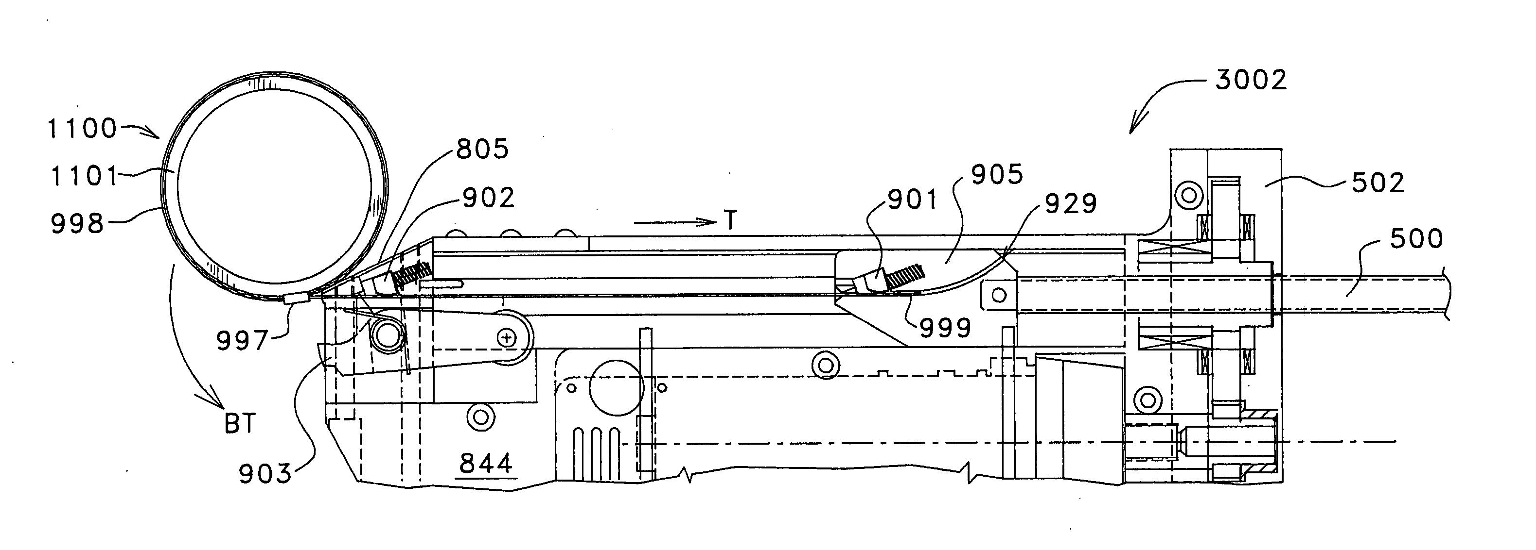
[0067] For applying a generic clamp assembly, the tail of the band is inserted into band entry port 70. Internal assemblies in the application module 3002 grip the tail,...


PUM

PropertyMeasurementUnit
Forceaaaaaaaaaa
Speedaaaaaaaaaa
Widthaaaaaaaaaa

Abstract

A portable electrically powered clamp application tool has a bench mounting kit with a foot pedal control for bench work. The tool has two grippers which enable a powered clamp cutting operation, wherein the only manual step is bending the tightened clamp prior to triggering the cutter arm. A gripper element is non-rotational and has teeth. It locates the material being gripped in a repeatable manner in spite of oil or other lubricants on the clamp. After the cutting operation an automatic release assembly releases the clamp. A manual lever(s) can also release a tail of a clamp.

Description

CROSS-REFERENCE TO RELATED APPLICATION [0001] The present application is a continuation in part claiming priority to non-provisional application Ser. No. 09 / 982,420 filed Oct. 17, 2001.FIELD OF INVENTION [0002] The present invention relates to a band application and cutting machine that pulls one end of a band loop around a workpiece via a powered jaw and then cuts the band via a powered cutter. BACKGROUND OF THE INVENTION [0003] The industrial applications for winding a metal band or hose clamp around a workpiece such as a hose to secure the hose to a pipe or fitting are well known in the art. One mechanical system is disclosed in U.S. Pat. No. 5,918,866 (1999) to Klimach. A metal band is wound around a workpiece, and then the two ends of the band are fed into two receiving ports on a manually operated strap clamping tool. The clamp is tightened under the effect of a double pulley. [0004] The closest known prior art is made by Band-It-Idex, Inc., a Unit of IDEX Corp., Denver, Colo....

Claims


Application Information

Patent Timeline
IPC IPC(8): B25B25/00B65B13/02B65B13/34
CPCB25B25/005B65B13/34B65B13/02
Inventor LENOX, WALTER W.
Owner ILLINOIS TOOL WORKS INC
Why Eureka
Try Eureka