
Tilted cavity semiconductor optoelectronic device and method of making same

a semiconductor optoelectronic and tilting cavity technology, applied in the field of tilting cavity semiconductor optoelectronic devices and methods, can solve problems such as wavelength-stabilized lasing

Inactive Publication Date: 2005-02-24
INNOLUME
View PDF15 Cites 72 Cited by
  • Summary
  • Abstract
  • Description
  • Claims
  • Application Information

AI Technical Summary

Problems solved by technology

This results in wavelength-selective leaky losses of the tilted optical mode to the substrate or contact layers, and thus, results in wavelength-stabilized lasing.

Method used


Image

  • Tilted cavity semiconductor optoelectronic device and method of making same
  • Tilted cavity semiconductor optoelectronic device and method of making same
  • Tilted cavity semiconductor optoelectronic device and method of making same

Examples


Embodiment Construction

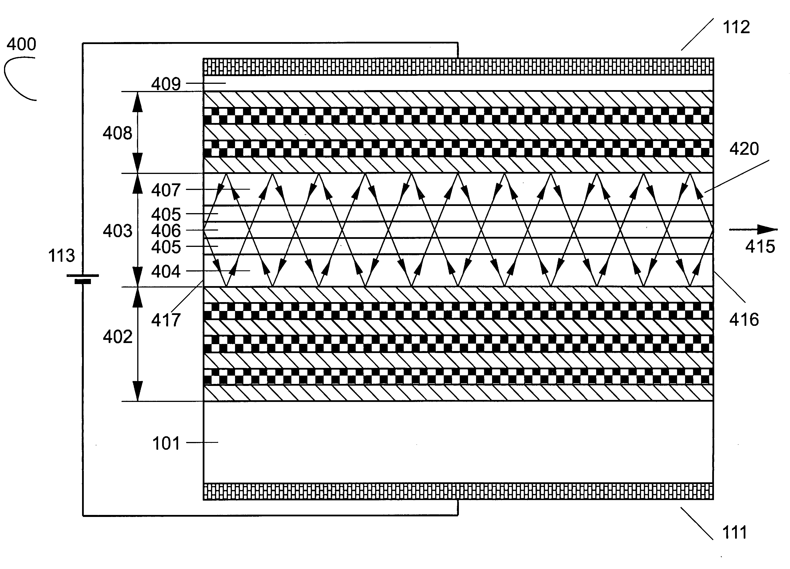
A way to overcome the shortcomings of both semiconductor diode lasers, switches, optical amplifiers, photodetectors, on the one hand, and light-emitting diodes, on the other hand, is related to the concept of a tilted cavity light-emitting device. This concept is based on the fundamental physical properties of multilayered structures, i.e, on the laws of propagation, transmission, and reflection of electromagnetic waves at oblique incidence. FIG. 3 illustrates the reflectivity spectrum of a periodic multilayered structure for a few different tilt angles of the propagating TE electromagnetic wave, as described by A. Yariv and P. Yeh, in Optical Waves in Crystals. Propagation and Control of Laser Radiation, Wiley, 1984. Light comes from the medium with a refractive index n1=3.6, and the structure includes 15 periods, each period further including one layer of the Λ / 2 thickness having a low refractive index n2=3.4 and one layer of equal Λ / 2 thickness having a high refractive index n1=3...


PUM


Abstract

A novel class of semiconductor light-emitting devices, or “tilted cavity light-emitting devices” is disclosed. The device includes at least one active element, generally placed within a cavity, with an active region generating an optical gain by injection of a current and two mirrors. The device generates optical modes that propagate in directions, which are tilted with respect to both the p-n junction plane and the direction normal to this plane. A light-emitting diode is also disclosed, where the cavity and the mirrors are designed such that transmission of generated optical power within a certain spectral range and within a certain interval of angles to the substrate is minimized. Transmission of optical power within a certain spectral range, which corresponds to the emission range of the light-emitting active medium and within a certain interval of angles out of the device, is optimized to achieve a required output power level.

Description

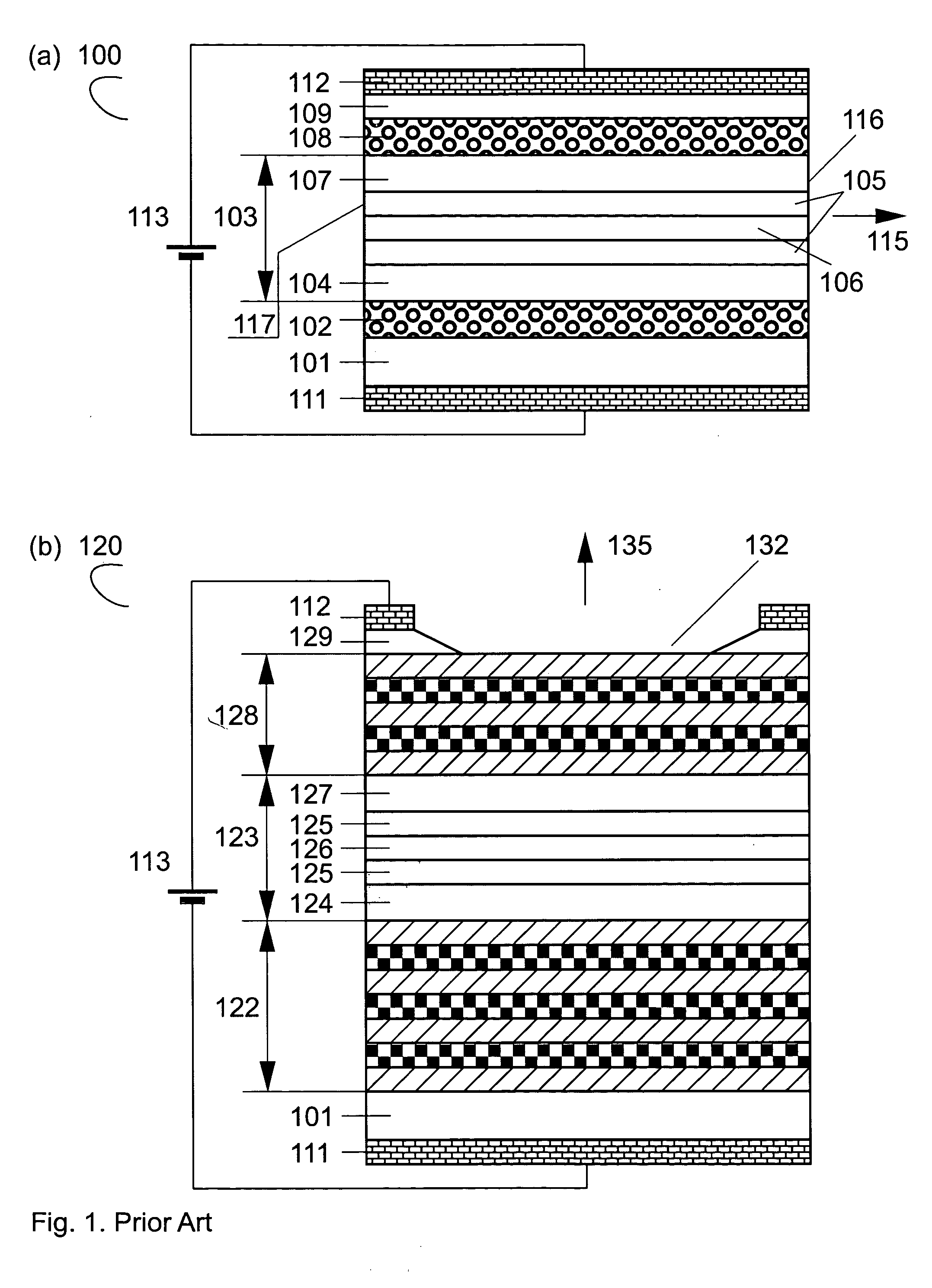
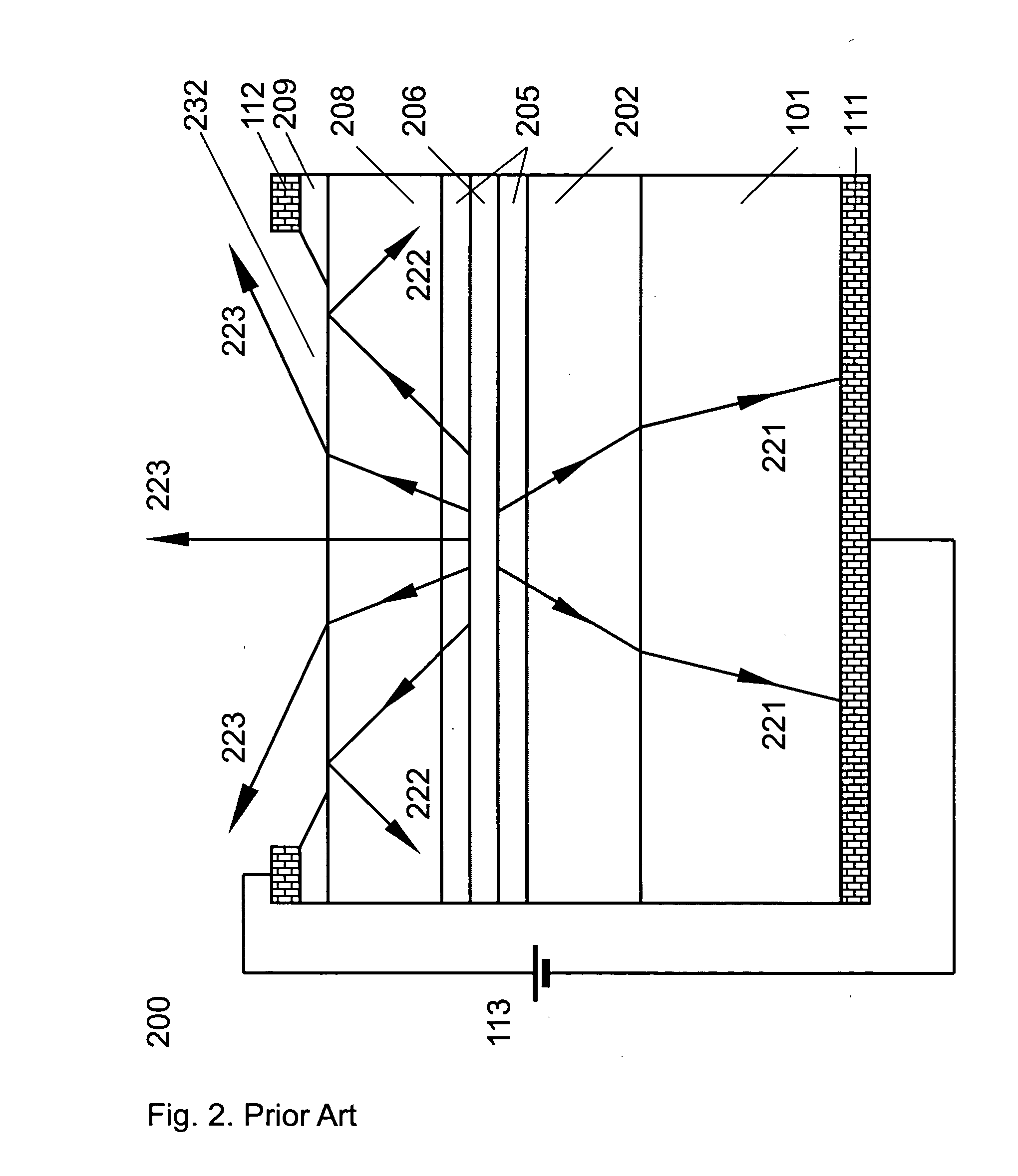
BACKGROUND OF THE INVENTION 1. Field of the Invention The invention pertains to the field of semiconductor devices. More particularly, the invention pertains to light-emitting diodes, wavelength-stabilized semiconductor edge-emitting and surface-emitting lasers, optical amplifiers, photodetectors, and mode-locked lasers. 2. Description of Related Art A prior art semiconductor diode laser, or more specifically, edge-emitting laser, is shown in FIG. 1(a). The laser structure (100) is grown epitaxially on an n-doped substrate (101). The structure further includes an n-doped cladding layer (102), a waveguide (103), a p-doped cladding layer (108), and a p-contact layer (109). The waveguide (103) includes an n-doped layer (104), a confinement layer (105) with an active region (106) inside the confinement layer, and a p-doped layer (107). The n-contact (111) is contiguous with the substrate (101). A p-contact (112) is mounted on the p-contact layer (109). The active region (106) genera...

Claims


Application Information

Patent Timeline
IPC IPC(8): H01L33/10H01S5/00H01S5/026H01S5/028H01S5/042H01S5/0625H01S5/10H01S5/14H01S5/16H01S5/18H01S5/183H01S5/20H01S5/223H01S5/50
CPCH01L33/105H01S5/50H01S5/0265H01S5/028H01S5/0425H01S5/06253H01S5/0654H01S5/1071H01S5/1085H01S5/141H01S5/162H01S5/18H01S5/183H01S5/2004H01S5/2027H01S5/204H01S5/2231H01S5/0028
Inventor LEDENTSOV, NIKOLAISHCHUKIN, VITALY
Owner INNOLUME
Learn More