
Frequency compensation scheme for low drop out voltage regulators using adaptive bias

Active Publication Date: 2005-02-24
DIALOG SEMICONDUCTOR
View PDF5 Cites 15 Cited by
  • Summary
  • Abstract
  • Description
  • Claims
  • Application Information

AI Technical Summary

Benefits of technology

A principal object of the present invention is to improve the stability of low dropout voltage regulators (LDO) having an adaptive biased driving stage.
A further object of the present invention is to keep the current consumption of said LDOs at a minimum.
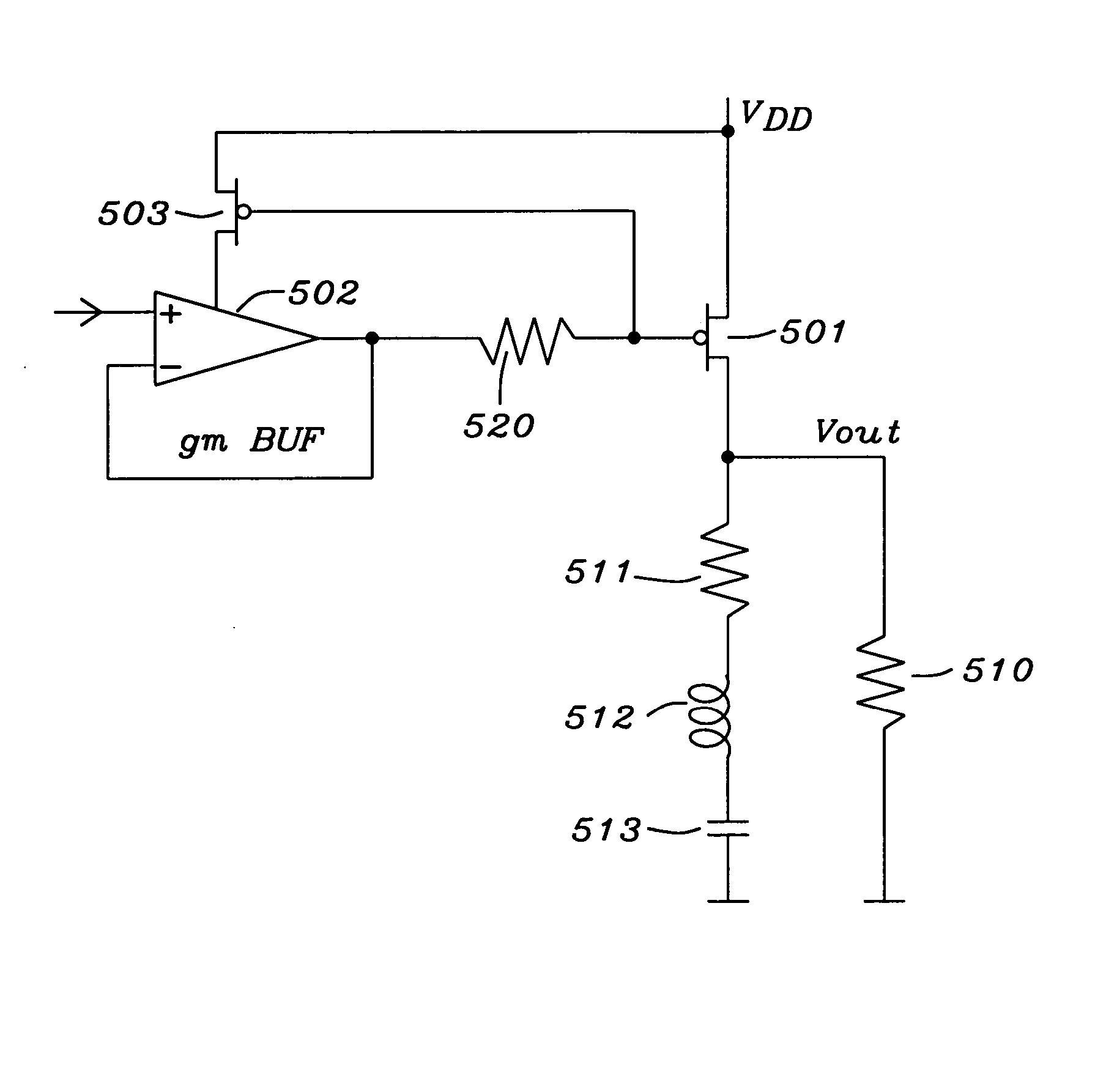
In accordance with the objects of this invention a circuit to improve the stability of a low drop-out (LDO) voltage regulator has been achieved. Said circuit comprises a means of an adaptive biased driving stage of said LDO, an impedance being connected on one side to said means of an adaptive biased driving stage and on the other side to the gate of a pass device of said LDO, a pass device of said LDO, wherein its gate is connected to said impedance and the source and drain are connected to VDD voltage and to the output voltage of said LDO, and a filter capacitor being connected to ground and to the output voltage of said LDO.
In accordance with the objects of the invention a method to improve the stability of a low drop-out (LDO) voltage regulator has been achieved. Said method comprises first providing a pass device for an adaptive biased driving stage. The steps of the method invented are to add a serial impedance to the gate capacitance of said pass device and to shunt partly said impedance in case of medium load currents as far as required.

Problems solved by technology

Conventional LDO regulators are very problematic in the area of transient response.
Voltage regulators are difficult to compensate because of the fact that the load resistance and with this the output pole can vary over a wide range.
Said frequency compensation is still a challenge for the designers of LDO regulators

Method used


Image

  • Frequency compensation scheme for low drop out voltage regulators using adaptive bias
  • Frequency compensation scheme for low drop out voltage regulators using adaptive bias
  • Frequency compensation scheme for low drop out voltage regulators using adaptive bias

Examples


Embodiment Construction

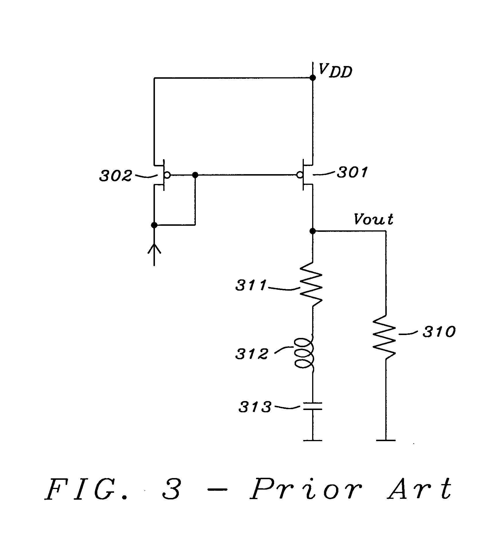
The preferred embodiments disclose circuits and a method for enhancements of low drop-out (LDO) voltage regulators having adaptive biased driving stages in order to improve the stability of the regulation loop of said LDOs. Said embodiments of the present invention can be used e.g. in multiple loop regulators as disclosed in U.S. Pat. No. 6,246,221 and described in the prior art section of this application or can be used e.g. with LDOs using current mirrors.

In order to achieve stability of the regulation loop of said LDOs it is necessary that the gate pole, formed by the inner resistance of the driving stage and the gate capacitance of the PMOS pass device, is at least N times higher than the output pole formed by load resistance and the load capacitance.

N has to be equal or higher than the open-loop gain of the LDO. For example, if the open-loop gain is 60 dB, i.e. 1000, then N has to be higher than 1000. This statement is only valid as long the inductances can be neglected. U...


PUM


Abstract

A method and circuits to improve the stability of low dropout voltage regulators having an adaptive biased driving stage. Said improvement of stabilization is valid through the total range of output current possible. A serial impedance is added to the gate capacitance of the PMOS pass device of said LDO. Said serial impedance could be a resistor or a transistor. In case of low load currents said impedance is not dominating, for high load currents said impedance keeps the gate pole close to the resonance frequency of the output tank. In case of medium load currents, wherein the inner resistance of the driving stage is about equal to said serial impedance, the gate pole could get too low. This problem is solved by reducing said serial impedance by shunting. Said shunting can be performed stepwise depending on the size of the load current. A special circuitry detects the condition of medium load currents and can initialize the shunting of said serial impedance accordingly in order to keep the gate pole on the optimum frequency.

Description

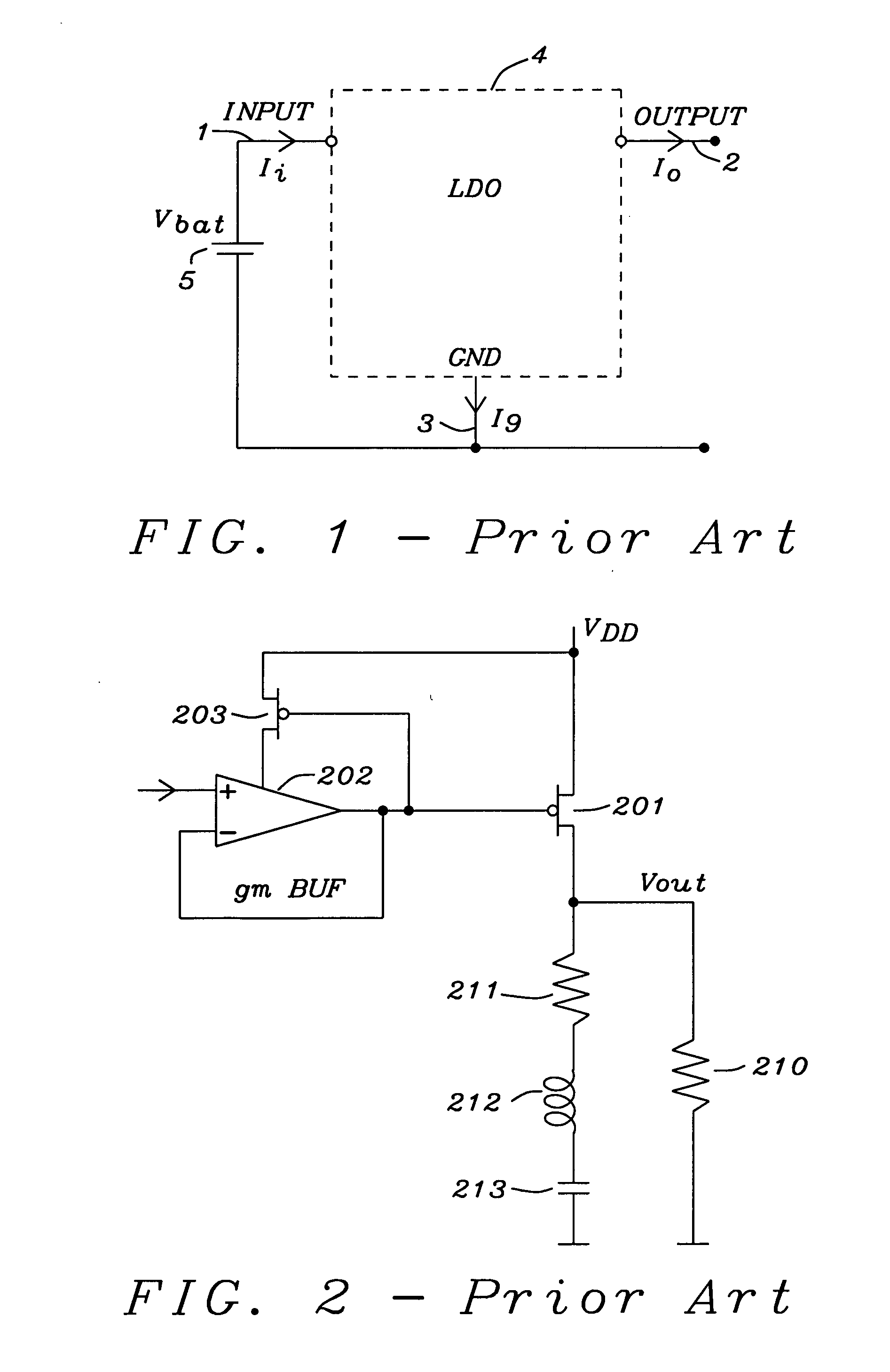
BACKGROUND OF THE INVENTION (1) Field of the Invention This invention relates generally to voltage regulators, and more particularly to an enhancement of low dropout voltage regulators having an adaptive biased driving stage in order to improve stability through a very wide range of output current. (2) Description of the Prior Art Low-dropout (LDO) linear regulators are commonly used to provide power to low-voltage digital and analog circuits, where point-of-load and line regulation is important. FIG. 1 prior art shows a typical basic circuit of a LDO regulator 3 having an input voltage Vi 1, an output voltage Vo 2, an input current Ii and an output current Io. Conventional LDO regulators are very problematic in the area of transient response. Transient response is the behavioral of the regulator after a abrupt change of either the load current (load response) or the input voltage (line response). A minimum under and overshoot of the regulated voltage and a fast settling is des...

Claims


Application Information

Patent Timeline
IPC IPC(8): G05F1/575
CPCG05F1/575
Inventor PANNWITZ, AXEL
Owner DIALOG SEMICONDUCTOR
Learn More