Liquid crystal display device and driving method thereof

a technology of liquid crystal display and driving method, which is applied in the direction of color television details, instruments, computing, etc., can solve the problems of slow processing speed and complex device structure, and achieve the effects of improving the apparent response speed of liquid crystal molecules, fast processing speed, and simple device structur

Inactive Publication Date: 2005-02-24
SHARP KK
View PDF4 Cites 13 Cited by
  • Summary
  • Abstract
  • Description
  • Claims
  • Application Information

AI Technical Summary

Benefits of technology

The present invention was made in view of the foregoing problems and an object of the present invention is to improve, with a simple device structure and a fast processing speed, image quality of displayed moving images by improving an apparent response speed of liquid crystal molecules by way of suppressing a mismatch in tone display by reducing a voltage change of pixel electrodes associated with a tone change of liquid crystal display elements.
Use of tone data exceeding this range causes luminance of the frame displayed by the tone data to be perceived as being widely different from the target luminance, i.e., from the luminance which corresponds to the tone indicated by the tone data of the display frame, and it may cause abnormal display in the subsequent frames. The foregoing method can prevent such problems.

Problems solved by technology

This requires a complex structure for the correction circuit and poses the problem of slow processing speed.
This requires a complex device structure.
Further, a technique such as that disclosed in the foregoing publication does not take into consideration the foregoing drawbacks caused by the capacitance change of the liquid crystal cell 22, and the foregoing publication does not teach a specific method of converting the data to solve these drawbacks.

Method used


Image

  • Liquid crystal display device and driving method thereof
  • Liquid crystal display device and driving method thereof
  • Liquid crystal display device and driving method thereof

Examples


first embodiment

[First Embodiment]

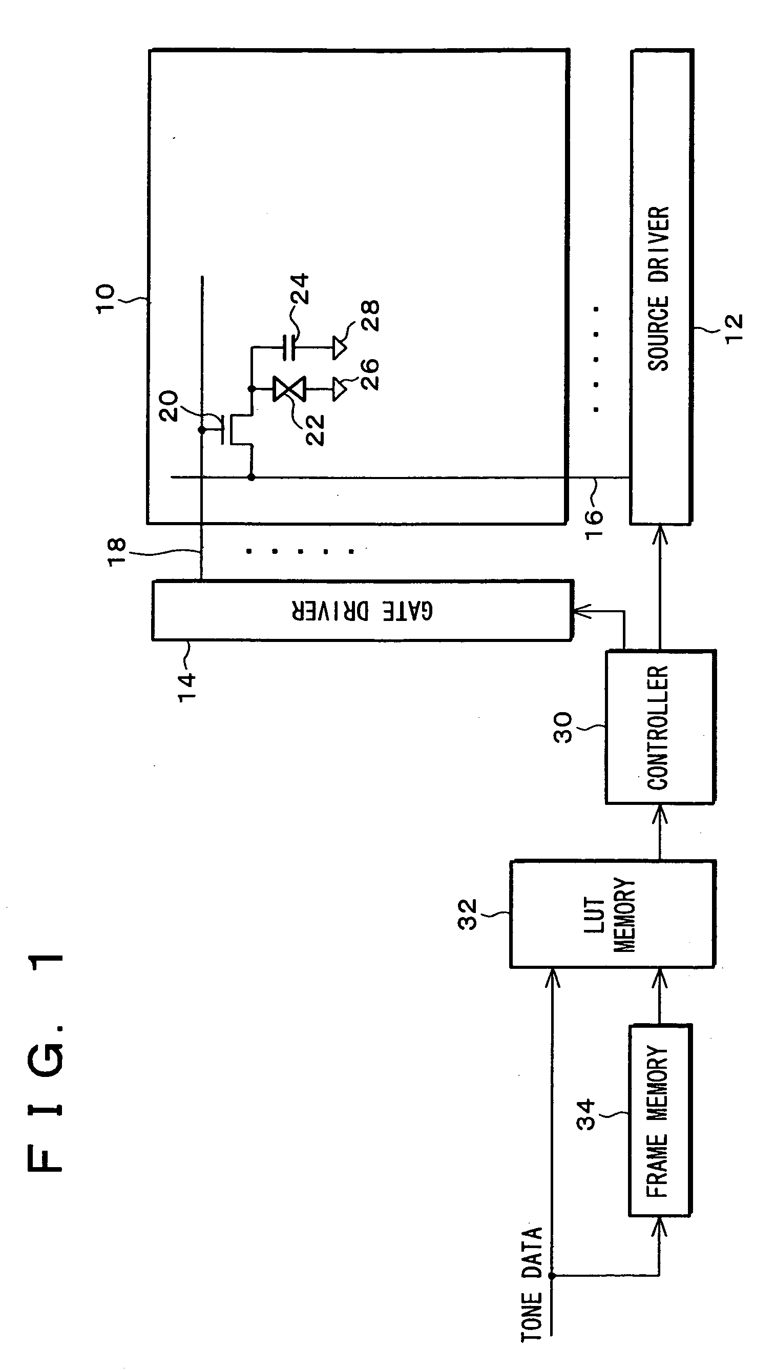
The following describes one embodiment of the present invention with reference to FIG. 1 through FIG. 11. FIG. 1 is a block diagram showing a structure of an active-matrix liquid crystal display device (LCD) according to the present embodiment. Note that, in FIG. 1, elements such as a liquid crystal panel 10, a source driver (driver) 12, and a gate driver 14 are the same as those described with reference to FIG. 14 in the BACKGROUND OF THE INVENTION section, and they are simplified in FIG. 1. Also, elements having the same functions as those described in FIG. 14 and FIG. 15 are given the same reference numerals and explanations thereof are omitted here.

The source driver 12 and the gate driver 14 are controlled by a controller (LCD controller, gate array) 30. From the controller 30 to the source driver 12 is sent tone data (image data) for specifying a tone voltage to be applied to each pixel via source bus lines 16. Here, the tone data is digital data. Further, ...

second embodiment

[Second Embodiment]

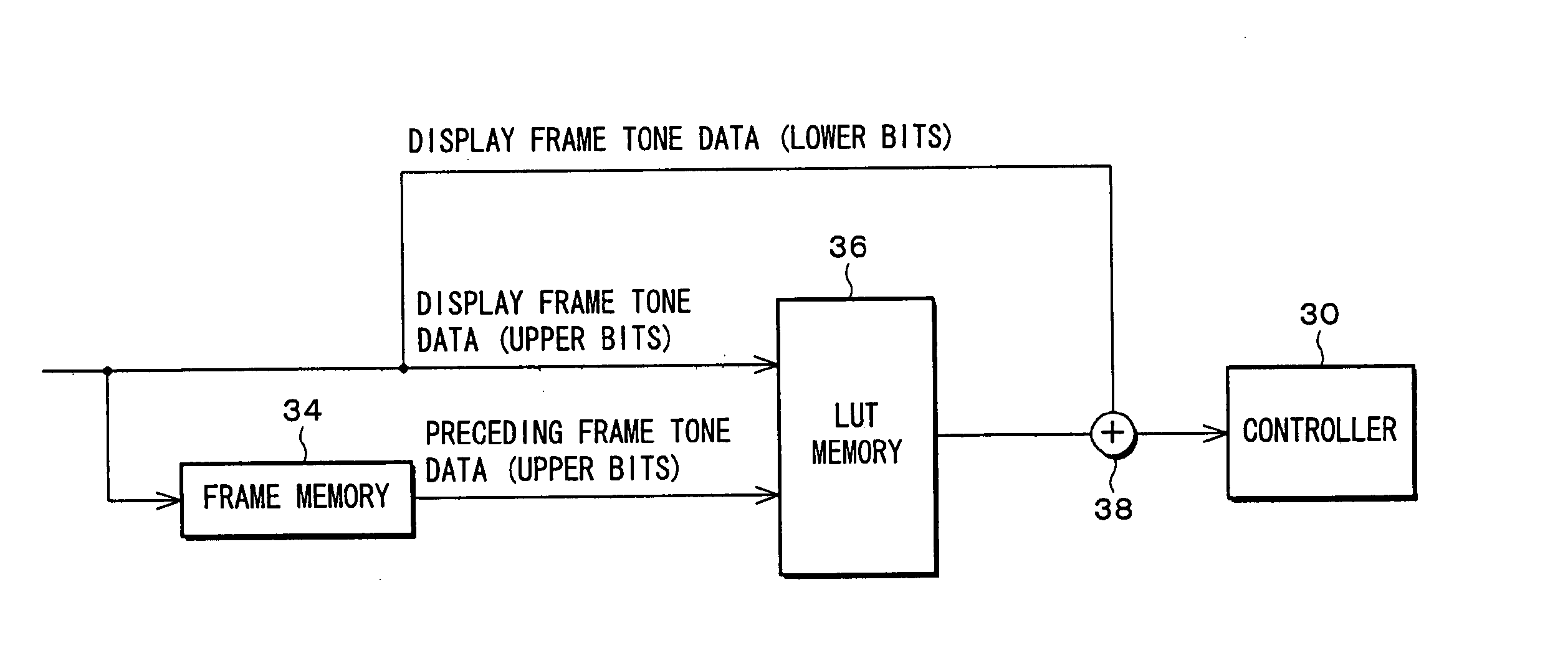
The following will describe the Second Embodiment of the present invention with reference to FIG. 16 through FIG. 19. An active-matrix liquid crystal display device of the present embodiment has a structure which is basically the same as that described in the First Embodiment based on FIG. 1, and only differences from the First Embodiment are described below. The active-matrix liquid crystal display device according to the present embodiment includes an LUT memory (convertor, memory) 36 instead of the LUT memory 32, and input and output of the LUT memory 36 are different from those of the First Embodiment.

FIG. 16 is a block diagram showing a structure surrounding the LUT memory 36 according to the present embodiment. The LUT memory 36 receives only upper bits (upper digits) of the respective display frame tone data and preceding frame tone data. The LUT memory 36 is adapted to output specific defined tone data from a predetermined look-up table which is stored i...

third embodiment

[Third Embodiment]

The following will describe the Third Embodiment of the present invention with reference to FIG. 20 through FIG. 25. An active-matrix liquid crystal display device of the present embodiment has a structure which is basically the same as that described in the First Embodiment based on FIG. 1, and only differences from the First Embodiment are described below. The active-matrix liquid crystal display device according to the present embodiment includes a converter / arithmetic circuit 40 instead of the LUT memory 32.

Conversion into appropriate tone data only by simple calculations based on the display frame tone data and the preceding frame tone data is difficult. This is because the calculations for conversion need to take into account (a) the voltage (Vm in Equation (4)) to be applied across the electrodes of the liquid crystal cell 22 according to a tone to be displayed and (b) a capacitance ratio (Cm / Cn in Equation (4)) across the electrodes of the liquid crystal...


PUM

PropertyMeasurementUnit
tone voltageaaaaaaaaaa
voltageaaaaaaaaaa
electric capacitanceaaaaaaaaaa

Abstract

A liquid crystal display device carries out tone display with pixels by applying a tone voltage according to tone data to each pixel in each frame, and includes: an LUT memory, which receives tone data of a display frame and tone data of an immediately preceding frame, for converting and outputting the tone data of the display frame; a source driver for applying the tone voltage to the pixels based on the converted tone data outputted from the LUT memory; and a liquid crystal cell, which makes up the pixels, for realizing tone display by the applied tone voltage, wherein the LUT memory stores beforehand output tone data which is specified by the tone data of the display frame and the tone data of the immediately preceding frame. This reduces a voltage change of pixel electrodes which is associated with a tone change to suppress unmatched tone display, thereby improving image quality of moving images.

Description

FIELD OF THE INVENTION The present invention relates to a liquid crystal display device which is capable of tone display and a driving method of such a liquid crystal display device. BACKGROUND OF THE INVENTION FIG. 14 is a schematic drawing showing a structure of a liquid crystal display device including a liquid crystal panel 10 of the active-matrix variety with thin-film transistors (“TFT” hereinafter) as the switching element, and drivers (source driver 12, gate driver 14) for driving the liquid crystal panel 10. The liquid crystal panel 10 includes a plurality of source bus lines 16 which are disposed parallel to one another in a vertical direction of the screen, and a plurality of scanning lines 18 which are disposed parallel to one another in a horizontal direction of the screen. Outside of the liquid crystal panel 10, the source bus lines 16 are connected to the source driver 12, and the scanning lines 18 are connected to the gate driver 14. The source bus lines 16 and the ...

Claims


Application Information

Patent Timeline
Patent Type & Authority Applications(United States)
IPC IPC(8): G09G3/20G09G3/36G02F1/133
CPCG09G3/3611G09G3/3648G09G2340/16G09G2320/0252G09G2320/0261G09G2320/02G09G3/36
Inventor MIYATA, HIDEKAZUSHIOMI, MAKOTOJINDA, AKIHITOTOMIZAWA, KAZUNARIMIYACHI, KOICHI
Owner SHARP KK
Why Eureka
Try Eureka