Signal processing device for acoustic transducer array

a transducer array and signal processing technology, applied in the direction of transducer details, electrical transducers, stereophonic arrangments, etc., can solve the problems of constructive interference, complex task of designing a functional and economically viable source of acoustic energy capable of projecting sound into predetermined directions, and spatial arrangement subject to technical constraints

Active Publication Date: 2005-02-24
YAMAHA CORP
View PDF55 Cites 69 Cited by
  • Summary
  • Abstract
  • Description
  • Claims
  • Application Information

AI Technical Summary

Problems solved by technology

The spatial arrangement in turn is subject to technical constraints arising from the technical properties of the transducers employed and costs.
Thus, the design of a functional and economically viable source of acoustic energy capable of projecting sound into predetermined directions, in short herein referred to as digital loudspeaker system or DLS, is a complex task.
Appropriate delays, which are frequency dependent, lead to a constructive interference at a predete

Method used


Image

  • Signal processing device for acoustic transducer array
  • Signal processing device for acoustic transducer array
  • Signal processing device for acoustic transducer array

Examples


Embodiment Construction

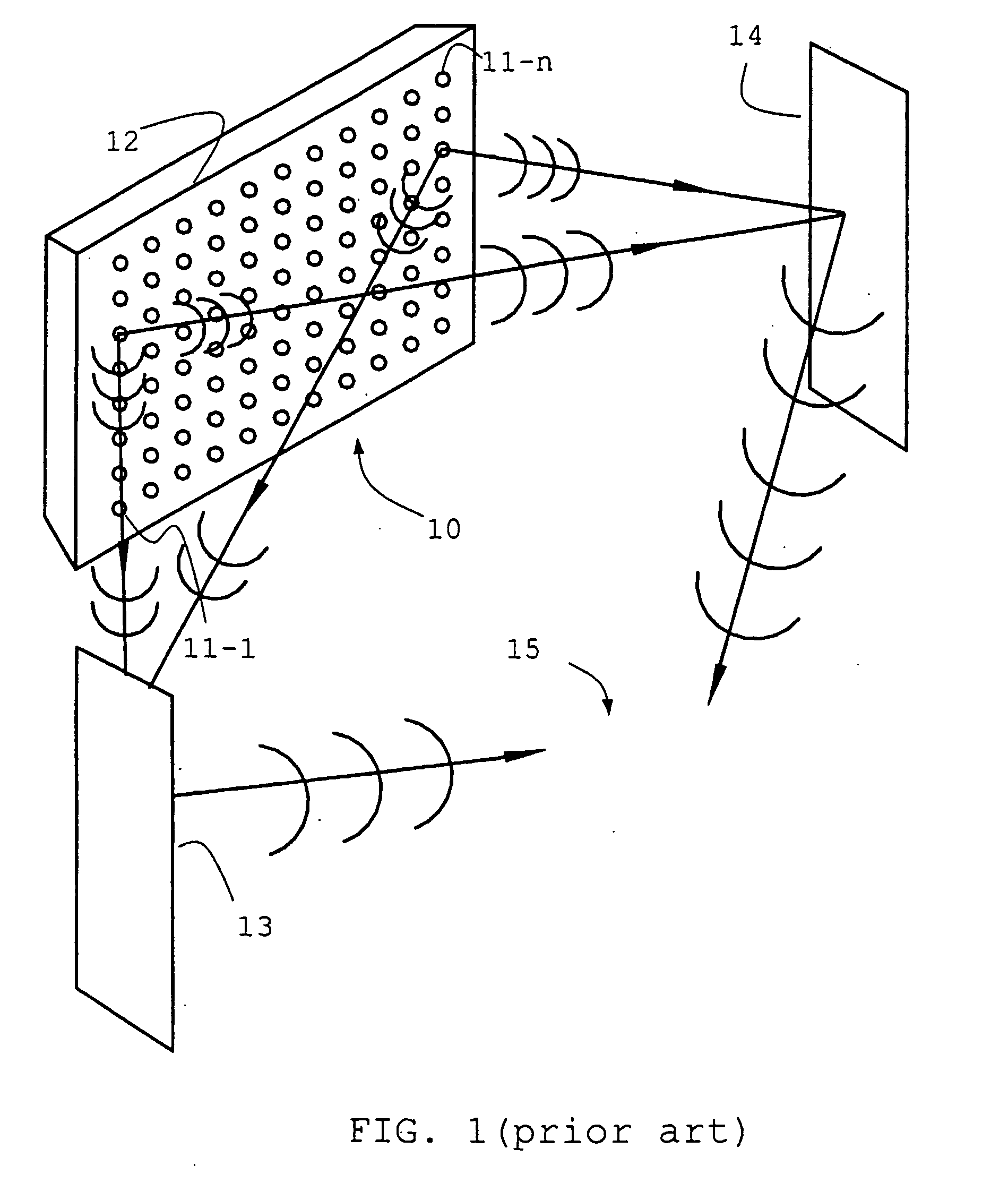
Firstly there is described a known arrangement of transducers capable of steering a beam of sonic signal into one or more predetermined directions, also referred to as DLS (Digital Loudspeaker System).

The basic arrangement of FIG. 1 shows an array 10 comprising a plurality of spatially-distributed electroacoustic transducers 11-1 to 11-n mounted on a common chassis 12 and arranged in an essentially two-dimensional array. The transducers 11 are each ultimately connected to the same digital signal input. This input is modified and distributed to feed the transducers. Beamsteering is accomplished by adding delays or phase shifts to the signal to ensure a constructive interference of the signals stemming from the individual transducers at pre-determined locations 13, 14. For the purpose of the present example, these location are spots on the side or rear wall of a room giving sufficient reflection to redirect the sound back to a listener 15 in the room. Basic geometric calculations s...


PUM


Abstract

The invention provides transducer arrays which are capable of outputting sound beams having a relatively constant width, and with minimal sidelobes, across a range of frequencies. This is achieved by utilising one or more digital signal modifiers within the signal path between the input sound signal and the array of transducers. Variable window functions are also disclosed.

Description

FIELD OF THE INVENTION This invention relates to steerable antennae and arrays of transducers, and concerns in particular arrays of electro-acoustic transducers. BACKGROUND OF THE INVENTION Steerable or phased array antennae are well known in the art in both the electromagnetic and the ultrasonic acoustic fields. They are less well known in the sonic (audible) acoustic area. The commonly-owned published International Patent application No WO 01 / 23104 describes sonic steerable or phased array antennae and their use to achieve a variety of effects. The application describes a method and apparatus for taking an input signal, replicating it a number of times and modifying each of the replicas before routing them to respective output transducers such that a desired sound field is created. This sound field may comprise a directed beam, focussed beam or a simulated origin. Control of direction and beamwidth, i.e. the steerability, of a beam is required to generate and steer broadband a...

Claims


Application Information

Patent Timeline
IPC IPC(8): H04R1/40H04R3/00H04R3/12
CPCH04R1/403H04R3/12H04R2205/022H04R2201/405H04R2203/12H04R2201/401H04R1/40
Inventor GOUDIE, ANGUS GAVINTROUGHTON, PAUL THOMASHOOLEY, ANTHONY
Owner YAMAHA CORP
Why Eureka
Try Eureka