Adjustable air foils for balancing pulverized coal flow at a coal pipe splitter junction

a splitter junction and air foil technology, applied in bulk conveyors, combustion processes, lighting and heating apparatus, etc., can solve the problems of burner imbalance, increased stack particulate emission levels, and different air flow rates of coal and primary air, so as to reduce the imbalance of coal flow and increase or decrease the flow of coal

Inactive Publication Date: 2005-02-24
LEVY EDWARD KENNETH +3
View PDF11 Cites 24 Cited by
  • Summary
  • Abstract
  • Description
  • Claims
  • Application Information

AI Technical Summary

Benefits of technology

The present invention includes riffler assemblies designed to lower coal flow imbalance (i.e. restore uniform particulate flow distribution). Furthermore, the present invention includes flow control elements (e.g. a plurality of wake-inducing airfoils) located just upstream of the riffler assembly to provide means for on-line coal flow adjustment / control. The present invention does not use direct diversion of the entire flow stream as described in Davis '001. Rather, it uses adjustable wake-inducing airfoils in the coal / air flow path to create air and particle wakes downstream of the obstacles. The air flow in the wake region behind the centerline of the airfoils has the lowest coal particle concentrations and velocities. Adjusting these wake-inducing airfoils relative to the flow channels of a slotted plate riffler makes it possible to increase or decrease the flow of coal into a particular outlet pipe without effecting primary air flow. Each wake-inducing airfoil has a cross-section defined by a width W that varies along its length H for creating upstream turbulence, and a particle wake that preferentially diverts the coal flow to one of the outlet pipes at the splitter junction without affecting primary air flow. Varying the width W along the height H results in a non-constant “Airfoil Thickness”, which is defined as the width of the airfoil profile. Thus, the wake-inducing airfoils of the present invention have a defined “aerodynamic center” corresponding to the point of maximum width, which induces an airflow that is accelerated over the airfoil and therefore produces a wake. The angle of attack can be varied to increase or decrease the pressure differential induced by the airfoil. With this in mind, the wake-inducing airfoils cannot have a constant Airfoil Thickness (like a flat vane) but may otherwise have a variety of suitable cross-sectional shapes in which width W varies along their length H to induce a wake. Suitable cross-sections include shapes from among the group consisting of teardrop, diamond, oval, triangle, circle, pentagon or others, so long as the cross-section from leading edge to back defines a non-constant Airfoil Thickness and is not simply a flat diverter vane. In each case the side surfaces may be roughened or textured to promote turbulent boundary layers. The combination of the riffler assembly and the wake-inducing airfoils make it possible to achieve on-line control of the flow distribution, and result in closely balanced coal flow in the outlet pipes.

Problems solved by technology

Unfortunately, differences in coal and primary air flow rates from one coal pipe 20 to the next are a limiting factor in the ability to reduce NOx emissions in pulverized coal boilers.
High carbon monoxide emissions and high levels of unburned carbon can result from burner imbalances.
High fly ash unburned carbon, in turn, can adversely affect electrostatic precipitator collection efficiency and result in elevated stack particulate emission levels.
Imbalances in coal pipe flows can also lead to maintenance problems associated with coal pipe erosion and / or clogging (e.g. excessive localized coal accumulation), damage to burners and windboxes, and accelerated waterwall wastage.
Problems such as these reduce the operating flexibility of the boiler and often require that the boiler be operated under conditions which produce higher NOx levels than would otherwise be achieved.
Industry experience shows that the coal flow rates among the four outlet pipes 106a-d can be severely imbalanced.
However, due to the space limitations associated with many applications / installations, a flow splitter has to be installed immediately after an elbow where, as stated above, the coal particulate exists as a narrow, localized rope flow.
The Wark '914 device restricts the combined coal and air flows, and does not teach or suggest controlling the direction of coal flow distribution into a plurality of outlet pipes without substantially interrupting air flow.
Field measurements show that while these types of rifflers can help to reduce coal flow imbalance arising from a mal-distribution of coal flow at the inlet, they generally do not eliminate the imbalance.
Guide vanes may be mounted inside the tiltable nozzle; however, this patent does not disclose adjustable guide vanes.
It is impossible using direct diversion to increase or decrease the flow of coal into a particular outlet pipe without effecting primary air flow, or vice versa.
In contrast, it is very difficult with an adjustable baffle approach to simultaneously balance coal and primary air flow rates.

Method used


Image

  • Adjustable air foils for balancing pulverized coal flow at a coal pipe splitter junction
  • Adjustable air foils for balancing pulverized coal flow at a coal pipe splitter junction
  • Adjustable air foils for balancing pulverized coal flow at a coal pipe splitter junction

Examples


Embodiment Construction

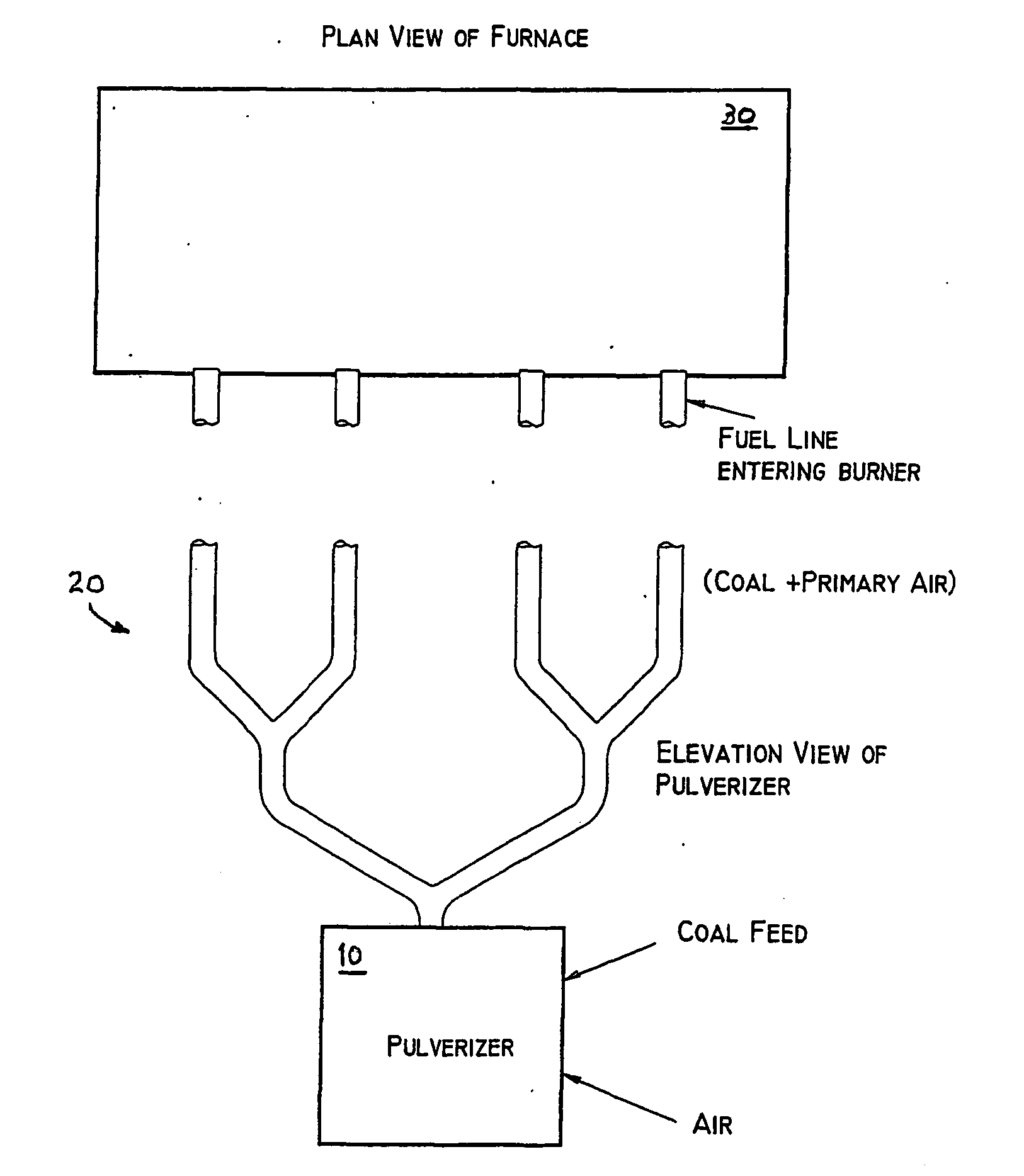
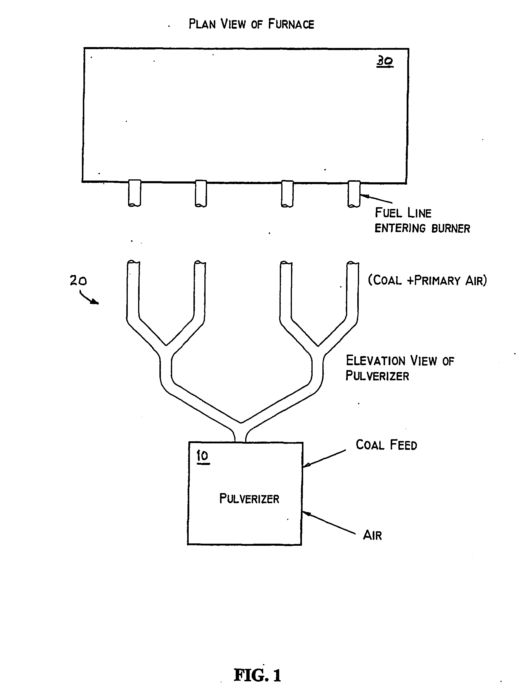
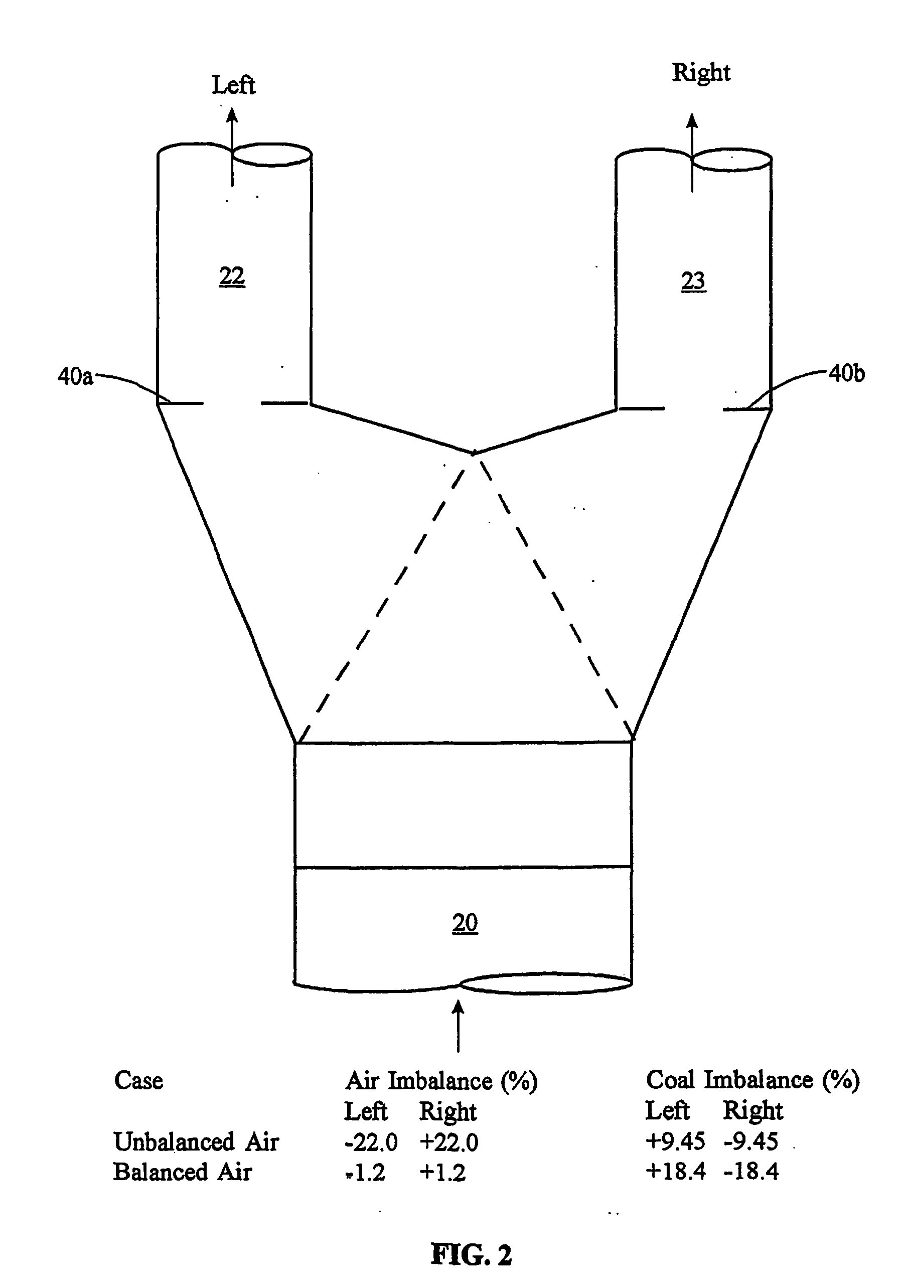
As described above, the distribution of primary air in most coal boilers must be controlled separately by use of orifice-type restrictions in individual pipes. It is important for good combustion that the mechanism for controlling the coal flow distribution have negligible effect on the distribution of primary air. The present invention offers a solution in the form of adjustable wake-inducing airfoils installed at the inlet of a slotted riffler, for on-line control of the distribution of coal among the outlet pipes. The wake-inducing airfoils create primary air and particle wakes, and the distribution of pulverized coal and primary air to the coal boiler can be manipulated by controlling the location, size and characteristics of the wakes via the wake-inducing airfoils.

More specifically, and as shown in FIG. 6, one embodiment of the present invention consists of an array of long air foil-like wake-inducing objects 60 that are placed just upstream of the inlet to a conventional r...


PUM


Abstract

An adjustable device installed at the inlet of conventional junctions/splitters (116) for on-line control of the distribution of coal among the outlet pipes is herein disclosed. The device includes a plurality of wake inducing airfoils (60) each positioned upstream of a plurality of flow channels in the riffler (50) for directing coal flow to the outlet pipes. Each wake-inducing airfoil has a cross-section defined by a width W that varies along its length H for creating upstream turbulence, and a particle wake that preferentially diverts the coal flow to one of the outlet pipes at the splitter junction without affecting primary air flow. For example, each wake inducing airfoil may comprise a rounded convex edge leading to straight tapered sides. The surfaces of the sides may be roughened or textured (63) for promoting turbulent boundary layers. In addition, conventional fixed or variable orifices may be used in combination with the wake inducing airfoils for balancing primary air flow rates. The device allows fine-adjustment control of coal flow rates when used in combination with the slotted riffler, yet it has negligible effect on the distribution of primary air, resulting in closely balanced coal flow, reduced pollutant emissions and improved combustion efficiency.

Description

BACKGROUND OF THE INVENTION 1. Field of the Invention The present invention relates to pulverized coal boilers and, more particularly, to adjustable air foils for balancing pulverized coal flow therein. 2. Description of the Background In a typical large pulverized coal boiler, coal particulate and primary air flow from the pulverizers to the burners through a network of fuel lines that are referred to as coal pipes. FIG. 1 illustrates a typical large pulverized coal boiler inclusive of pulverizer(s) 10, furnace 30, and network of coal pipes 20. For proper operation of the boiler, all the coal pipes 20 connected to any one of the pulverizers 10 should carry the same coal flow rates and the same flow rates of primary air. Unfortunately, differences in coal and primary air flow rates from one coal pipe 20 to the next are a limiting factor in the ability to reduce NOx emissions in pulverized coal boilers. High carbon monoxide emissions and high levels of unburned carbon can result...

Claims


Application Information

Patent Timeline
Patent Type & Authority Applications(United States)
IPC IPC(8): F23K3/02
CPCF23K3/02F23K2203/201F23K2203/105F23K2203/006
Inventor LEVY, KENNETHBILIRGEN, HARUN
Owner LEVY EDWARD KENNETH
Why Eureka
Try Eureka