Controller of permanent magnet generator

a permanent magnet generator and controller technology, applied in the control system of electric generators, control systems, electrical apparatus, etc., can solve the problems of increasing the current flow, reducing the efficiency of the generator, and requiring energy saving, so as to increase the current flow and reduce the current flow

Inactive Publication Date: 2009-06-30
KAWAMURA MEGUMI +1
View PDF4 Cites 35 Cited by
  • Summary
  • Abstract
  • Description
  • Claims
  • Application Information

AI Technical Summary

Benefits of technology

[0017]Here, in the controller of the permanent magnet generator according to the present invention, a voltage of the power terminal of the power coil and a voltage of the control coil have a relationship of the output side voltage=the control side voltage×(the output side number of windings) / (the control side number of windings), and can increase and decrease the current amount flowing into the control coil by the switch.
[0026]The controller of the permanent magnet generator which composed with winding coil having small winding number for power coil and larger winding number whose coils are connected in series, and than power coil connected with the control coil in series, adjust the current flowing into the control coil which used the character of reducing voltage largely by flowing small current in the control coil having a large number of windings to maintain constant voltage in the power coil. Generally, the voltage of winding coil reduces it when generated current increase, and the winding number of coil increase larger, the ratio of downward voltage larger as shown in FIG. 2. Those two kind of coils are installed in parallel in the many further disclosed in Japanese patents, and they tried to control the power coil voltage by flowing current into the coil having a large number of windings, however large amount of current is required to reduce the magnetic force even if the control coil winding number is very large, then they have not succeeded in the technologies. However when small winding number of coil for power coil is connected with large winding number for control coil in series in order to produce opposite electromotive force in the coil, as shown in the invention, we can control the power coil voltage due to flowing current into the control coil, because the voltage of winding coil in the generator is in proportion to winding number and power coil voltage follow the changing the voltage of control coil directory. In other wards, when it is set up that N1 is small number of windings in power coil and N2 is large number of windings in control coil, the voltage V1 of power coil is the value in the equation shown as following: V1=V2×N1 / N2 The equation is shown as follows.E0=4.44·Φ·f·Ws  (1)E=E0−I1·(R12+(2π·f·L1 / 1000)2)1 / 2−I2·(R22+(2π·f·L2 / 1000)1 / 2  (2)E0: voltage of electromotive forceE: terminal voltageΦ: magnetic forcef: frequency of generatingWs: winding number of coilI1: current of power coilI2: current of control coilR1: resistance of power coilR2: resistance of control coilL1: inductance of power coilL2: inductance of control coil

Problems solved by technology

So far, the improvement of efficiency in a generator has been big problem in the requirement of energy saving.
However it has been difficult to use the permanent magnet (PM) generator for such as automotive vehicle because the generated voltage is changed up and down as generator speed change.
Many researchers have carried out to research how to control the voltage constantly in PM generator, and the method of controlling the voltage constantly used switching regulator was developed by GM however the system had big problems such as large size of controller, expensive and low efficiency.
In order to make the voltage constantly, the electric voltage should be chopped in the switching regulator which is used big size of power transistors, as the result the system was increased in the size, cooling system and cost.
On the other hand, the spike of current sometimes produced when the electric power was chopped and the spike pulled the trigger of obstacle in a radio wave then the countermeasure of noise become very difficult problems.
However it is very difficult to weaken magnetic force of permanent magnet in response to increasing rotor speed to the higher by using the methods mentioned above and those technologies have not realized in practical use.
However those were disturbed by complicated and large size of the system to be diffused them in the automotive market.
On the other hand, energy problems become worse recently, and about 50% efficiency in the Lundell type generator has not permitted yet in conventional vehicles.
In order to reduce the magnetic flux of PM force which flows into stator, the magnetic flux produced by current flowing from an inverter need to be similar shapes to PM flux, however those techniques were very difficult.
Furthermore, those electric magnetic flux opposed to PM flux makes the magnetic force of PM material reduce and they suffered with the trouble of generator.

Method used


Image

  • Controller of permanent magnet generator
  • Controller of permanent magnet generator
  • Controller of permanent magnet generator

Examples


Embodiment Construction

[0040]A generator controlled voltage by winding coil combined with control coil and power coil in accordance with the present invention will be hereinafter described with reference to the accompany drawings.

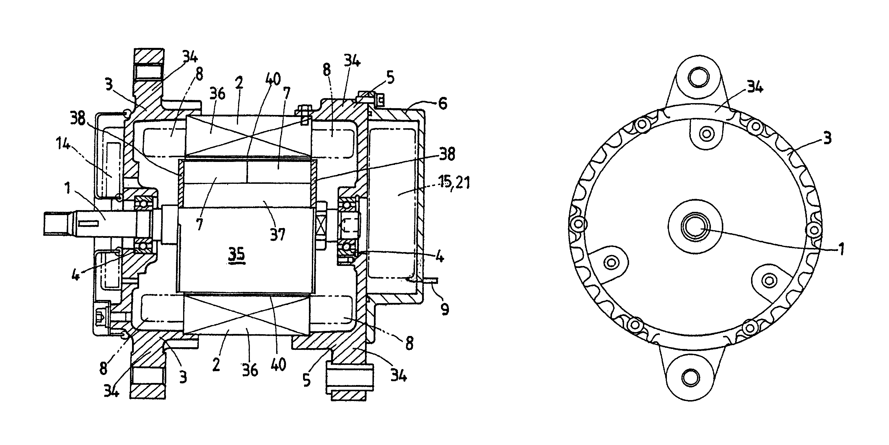
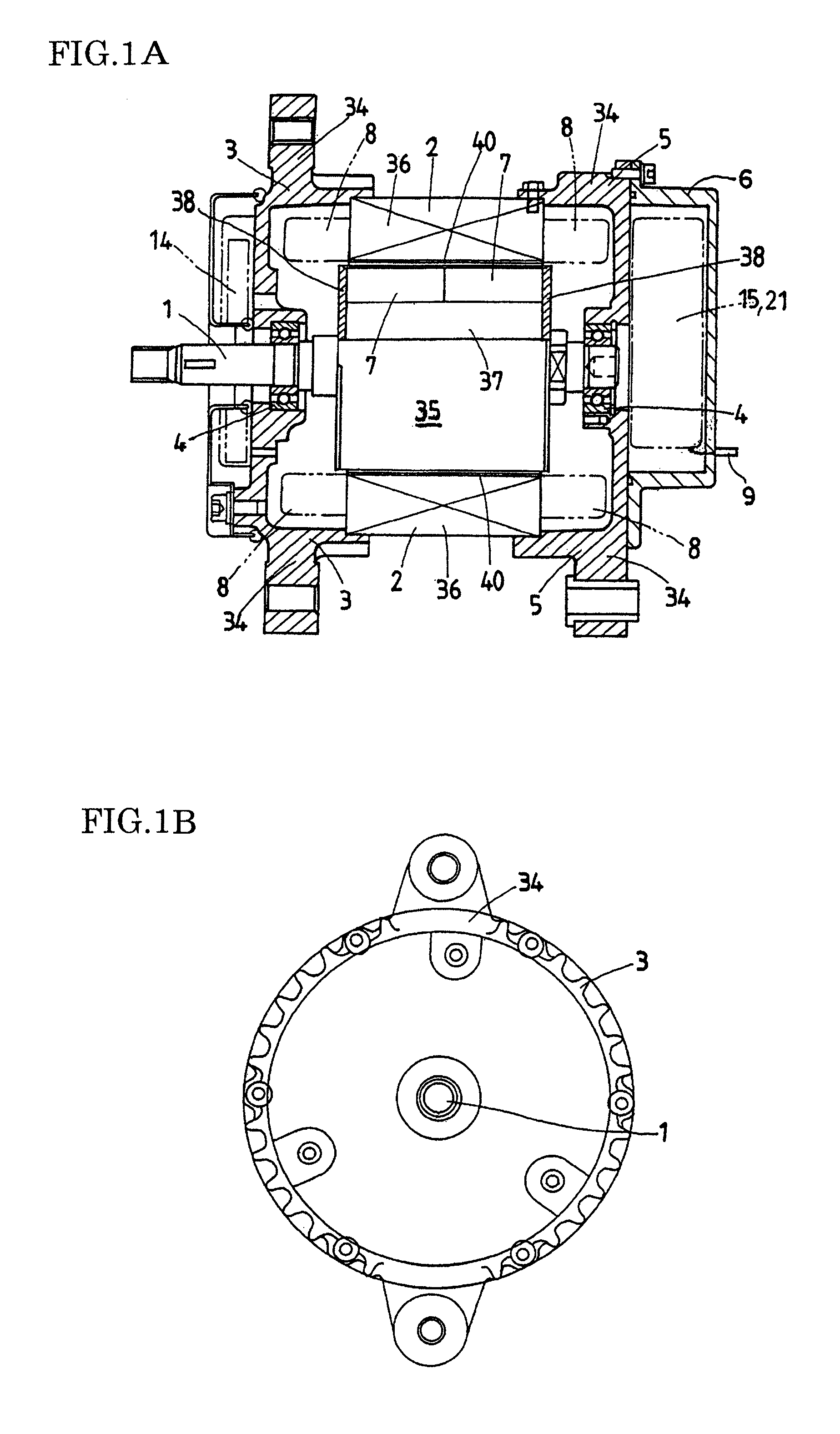
[0041]The permanent magnet generator controlled voltage by winding coils as shown in FIG. 1, is comprised of stator hosing 34 which is a pair of housing halved housing 3 and 5, a rotor shaft 1 supported for rotation in the housing 3 and 5 by means of a pear of axially opposite ball bearings 4, a rotor 35 of a multi-polar permanent magnet member 7 in which more than one platy permanent magnet pieces is arranged circumferentially around the rotor shaft 1, a stator 2 arranged around the outer periphery of the rotor 35. The stator 2 is composed by stator core 36 and rolled up by electromagnetic coils 8 arranged in stator core 36. An equipment of driving such as pulley is fixed to the end of rotor shaft 1, which is not shown in FIG. 1. The rotor shaft 1 is composed of a magnetic perme...


PUM


Abstract

The controller of permanent magnet generator controls the current by using control switch which is installed in between power coil and control coil and switches on and off in switches in order to generate two different voltage and increase the power at very low speed condition of generator. The controller controls the voltage of power coil constantly by adjusting current of flowing in the control switch which the voltage is sensed on the load voltage sensor and the controller control the voltage constantly at very small speed by using power switches furthermore, the controller controls the two kind of voltage in power coils constantly by using control switch and switches in case of the generator having different kind of voltages.

Description

TECHNICAL FIELD[0001]The present invention relates to a permanent magnet generator with a controller to maintain constant voltage, which is comprised of a rotor installed permanent magnet pieces supported for rotation in a stator housing, a stator surrounding around an outside periphery of the rotor, stator coils contained a power and a control coil and controller to keep a voltage constantly.BACKGROUND OF THE INVENTION[0002]So far, the improvement of efficiency in a generator has been big problem in the requirement of energy saving. In the structure of the generator, electrical magnet is used for a rotor mainly, which is produced magnetic force by flowing current in a coil installed in the rotor. They know well that the efficiency is improved on the generator by use of a permanent magnet rotor because it is no need to use a current for producing magnetic force. However it has been difficult to use the permanent magnet (PM) generator for such as automotive vehicle because the genera...

Claims


Application Information

Patent Timeline
Patent Type & Authority Patents(United States)
IPC IPC(8): H02P9/14
CPCH02P9/14H02P9/48H02P2101/45H02P2207/076H02P2101/15H02P2207/05H02K3/18H02P9/38H02P27/16
Inventor KAWAMURA, HIDEO
Owner KAWAMURA MEGUMI
Why Eureka
Try Eureka