Method and arrangement for the rapid connection and detachment of connectable elements

a technology of connectable elements and connections, applied in the direction of couplings, couplings, coupling devices, etc., to achieve the effect of simple and reliable relative rotary movement, reliable force transmission, and convenient fitting

Inactive Publication Date: 2005-02-24
PAUL WURTH SA +1
View PDF12 Cites 28 Cited by
  • Summary
  • Abstract
  • Description
  • Claims
  • Application Information

AI Technical Summary

Benefits of technology

[0010] In order to enable simple and reliable relative rotary movement between the individual elements to be connected, between the two moving procedures each in the axial direction or direction of connection, it is proposed according to a further preferred embodiment that the intermediately located region of the reception opening having an enlarged clear cross section has a length in the axial direction or connection direction, which exceeds the axial extension of the profile of the end piece to be received. In order to ensure proper anchorage of the two elements to be connected, the end piece of the first element must be provided with an outer profile of appropriate length so as to enable also the subsequent transmission of possibly large forces, for instance, during drilling or rotary percussion drilling. By appropriately choosing a profile, an optionally short length of the outer profile will do and it is, therefore, feasible to make the portion or region to be provided for enabling rotary movement accordingly short in the region of the reception end.
[0011] In order to render feasible a profile easy to fit in, which, in addition, ensures a reliable force transmission between the individual elements to be connected by accordingly large bearing surfaces, it is proposed according to a further preferred embodiment that the profile on the end piece to be received is formed by a regular polygon. Particularly in the context of simple processing and manufacturing of the connection regions to be connected, it is proposed according to a further preferred embodiment that the polygon has a triangular cross section having rounded tips or vertices.
[0012] For a particularly simple configuration of the differently designed partial regions in the region of the reception opening of the second element or connection or intermediate piece, it is proposed according to a further preferred embodiment that the profile on the entry end of the reception opening is formed on a separate plate-shaped or disc-shaped element connected, particularly welded, with the receiving element. It is, thus, feasible in a simple manner in the region of the reception opening to form with accordingly complementary profiles the region having an enlarged clear cross section to allow for the rotary movement and, following thereupon, the region extending in the axial direction, whereupon the plate-shaped or disc-shaped element likewise having a profile complementary to said profile is fixed to the connection end or entry end of the reception opening in an offset manner in the interior of the reception opening.

Problems solved by technology

In the context of connecting and detaching connectable elements such as, for instance, tubes or rods, there is often the problem of rapidly detaching and connecting such elements or driving elements and / or working elements to be connected therewith, such a rapid connection or detachment, if necessary, having to be reliably feasible or realizable even under rough and adverse environmental conditions.
In the context of the production of bore holes, for instance, the extension of a drill rod assembly is frequently necessary, wherein known screw connections not only call for time-consuming connecting and detaching procedures, but such screw connections may entail problems relating to the proper connection or proper detachment of such a connection, particularly under rough conditions of use.

Method used


Image

  • Method and arrangement for the rapid connection and detachment of connectable elements
  • Method and arrangement for the rapid connection and detachment of connectable elements
  • Method and arrangement for the rapid connection and detachment of connectable elements

Examples


Embodiment Construction

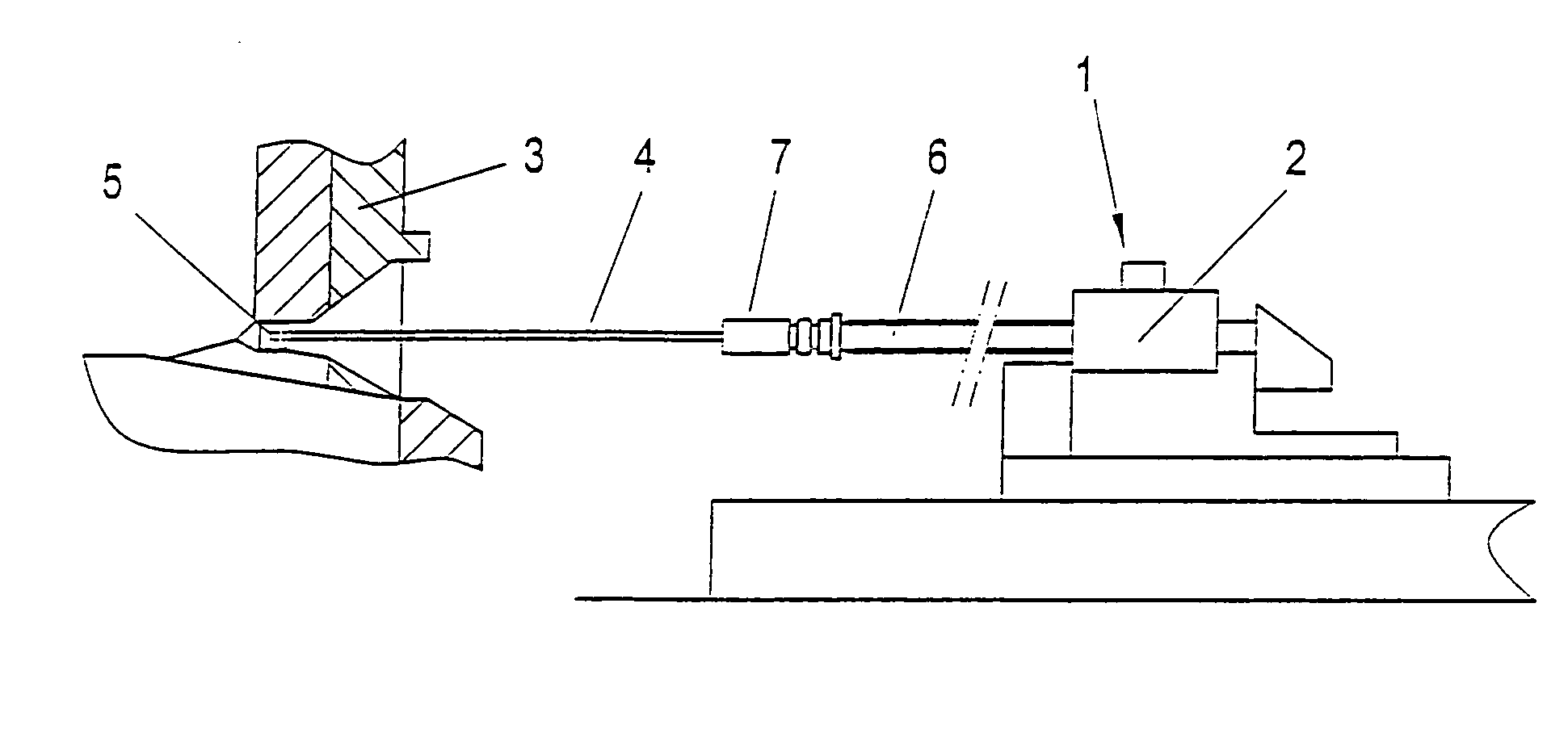
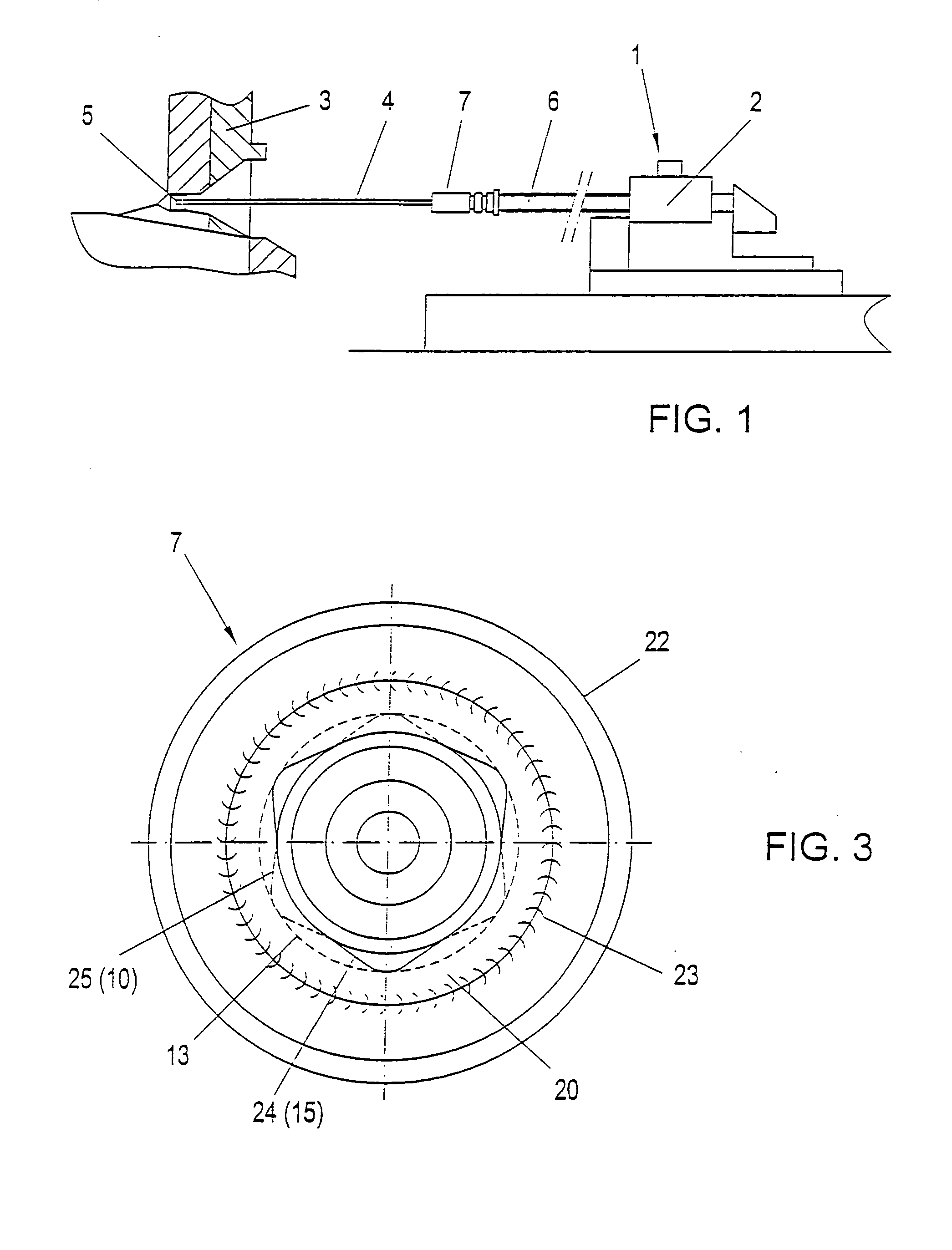
[0018] In FIG. 1, a tap-hole drilling machine, in general, is schematically denoted by 1, comprising an actuating means 2 to form a tap hole or bore hole in a blast furnace wall schematically indicated by 3, a drill bit schematically indicated by 5 being mounted on a drill rod assembly 4.

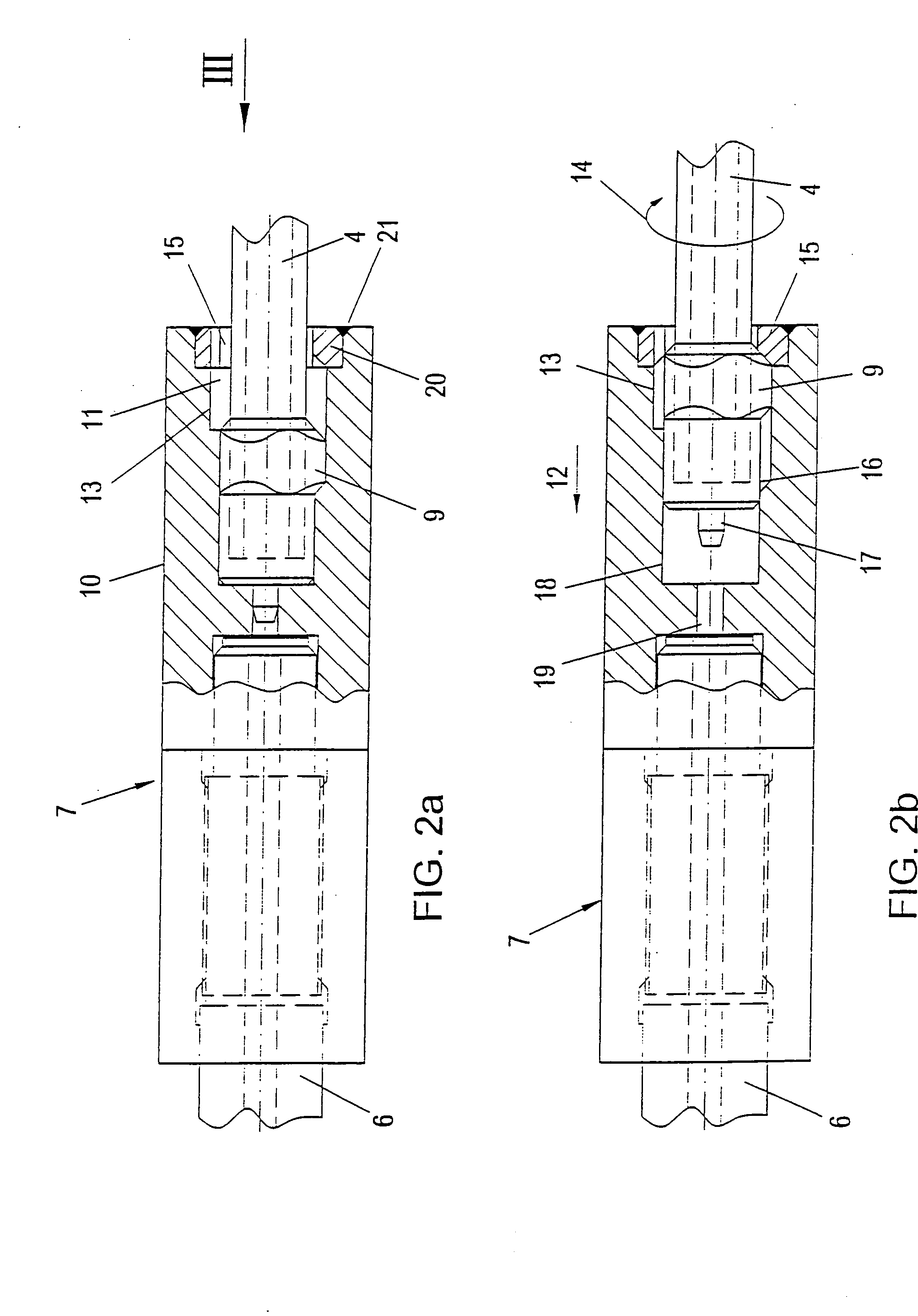
[0019] In order to fix the drill rod assembly 4 to a driven shaft 6 of the percussion and / or rotary drive of the tap-hole drilling machine 1, the drill rod assembly 4 is fixed via an intermediate element generally denoted by 7 in FIG. 1, of an arrangement for connecting the two rod-shaped or tubular elements 4 and 6, which is illustrated in more detail in FIG. 2.

[0020] In order to connect the region of the driven shaft 6 of the tap-hole drilling machine 1 with the drill rod assembly 4, the embodiment represented in FIG. 2 comprises a connection or intermediate element 7 forming said arrangement, the driven shaft 6 being firmly received in the intermediate element 7 in the left-hand partial region ...


PUM


Abstract

In a method and an arrangement for the rapid connection and detachment of connectable elements (4, 6), particularly tubes or rods and/or driving elements and/or working elements capable of being fixed thereto such as, for instance, drill bits or the like, wherein an element (4) having a profiled end piece (9) is introduced into a respective reception opening (11) of the element (6) to be connected therewith and/or an intermediate or connection piece (7), particularly a bushing or sleeve, and connected with the second element (6) in a positive and force-transmitting manner, it is provided that, for the connection and detachment of the two elements (4, 6) to be connected, the profiled end piece (9) after a movement in the axial or connection direction (12) is rotated, by a partial region (15) of the reception opening (11) provided with a profile complementary to that of the end piece, relative to the reception opening (11) in a partial region (13) of the reception opening (11) having an enlarged clear cross section, and subsequently is again moved in the axial direction (12) into a further partial region (10) of the reception opening (11) provided with a profile complementary to that of the end piece (9), thus enabling rapid and simple connection and detachment at structurally simple expenses.

Description

[0001] The present application is a continuation application of PCT / AT03 / 00152, filed on May 27, 2003.FIELD OF THE INVENTION [0002] The present invention relates to a method for the rapid connection and detachment of connectable elements, particularly tubes or rods and / or driving elements and / or working elements capable of being fixed thereto such as, for instance, drill bits or the like, wherein an element having a profiled end piece is introduced into a respective reception opening of the element to be connected therewith and / or an intermediate or connection piece, particularly a bushing or sleeve, and connected with the second element in a positive and force-transmitting manner. The invention, furthermore, relates to an arrangement for the rapid connection and detachment of connectable elements, particularly tubes or rods and / or driving elements and / or working elements capable of being fixed thereto such as, for instance, drill bits or the like, wherein an element having a profil...

Claims


Application Information

Patent Timeline
Patent Type & Authority Applications(United States)
IPC IPC(8): E21B17/03E21B17/046E21B17/07F16D1/10F16D1/112
CPCE21B17/03E21B17/046F16D1/112F16D1/10E21B17/076
Inventor MOCIVNIK, JOSEFLONARDI, EMILE
Owner PAUL WURTH SA
Why Eureka
Try Eureka