Position pointing device

a technology of position pointing and pointing device, which is applied in the direction of mechanical pattern conversion, electric unknown time interval measurement, setting time indication, etc., can solve the problems of difficult to change the type of pointing device information or the number of bits to be returned, and the above-described position pointing device has some problems, and achieves low power and battery-less operation.

Inactive Publication Date: 2005-02-24
WACOM CO LTD
View PDF3 Cites 28 Cited by
  • Summary
  • Abstract
  • Description
  • Claims
  • Application Information

AI Technical Summary

Benefits of technology

[0008] Accordingly, an object of the present invention is to provide a technology that can achieve a battery-less operation with low power transmitted from a tablet.

Problems solved by technology

The above-described position pointing devices have some problems.
This makes it difficult to change the type of pointing-device information or the number of bits to be returned and also makes it impossible to provide a position pointing device that serve purposes.
Additionally, cost for design is high.

Method used


Image

  • Position pointing device
  • Position pointing device
  • Position pointing device

Examples


first embodiment

[0049] First Embodiment

[0050] Configuration of First Embodiment

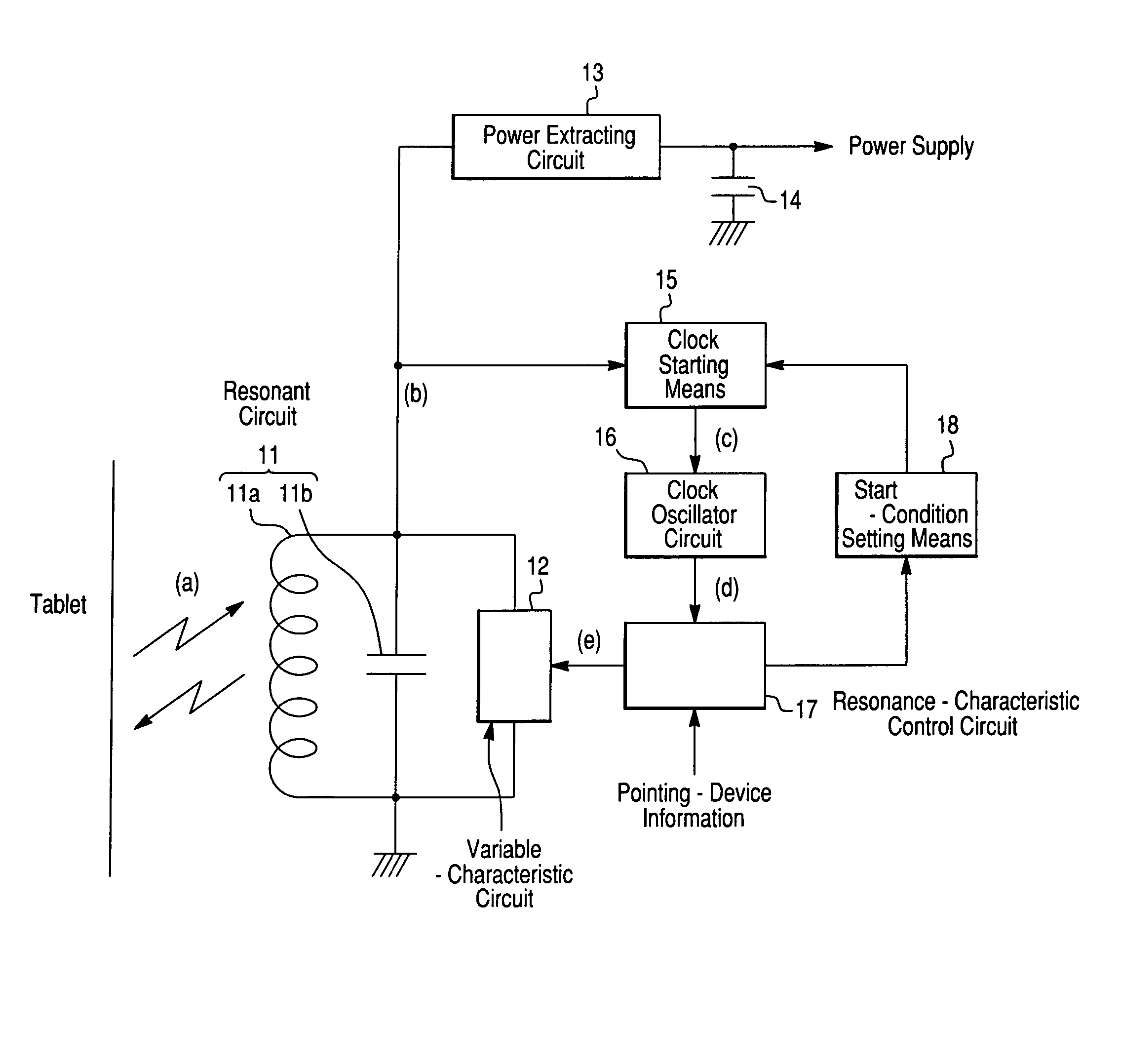
[0051]FIG. 3 shows the configuration of a position pointing device according to a first embodiment of the present invention. The same elements and portions as those shown in FIG. 1 are denoted with the same reference numerals. The position pointing device of the present embodiment generally includes a resonant circuit 11, a power extracting circuit 13, a power-supply capacitor 14, capacitors 21 and 29, a switch 22, a detection circuit 23, comparators 24 and 26, an integration circuit 25, a microprocessor or CPU 27, and a resistor 28.

[0052] The capacitor 21 has a considerably small capacitance compared to a capacitor lib and is connected to two opposite ends of the capacitor 11b via the switch 22. The resonant frequency of the resonant circuit 11 is slightly changed in response to the turning on or off of the switch 22.

[0053] The detection circuit 23 and the comparator 24 supply a signal to the CPU 27 in accordance wit...

second embodiment

[0079] Second Embodiment

[0080] Configuration of Second Embodiment

[0081]FIG. 7 is a circuit diagram of a position pointing device according to a second embodiment of the present invention. In this example, a continuous amount corresponding to an operation of the position pointing device is detected and returned. In FIG. 7, the same elements and portions as those shown in FIG. 3 are denoted with the same reference numerals. The position pointing device according to the second embodiment generally includes a resonant circuit 11, a power extracting circuit 13, a power-supply capacitor 14, a switch 22, a detection circuit 23, comparators 24 and 26, an integration circuit 25, resistors 28, 32, and 35, capacitors 29 and 34, a CPU 31, and a pressure-sensitive resistance element 33.

[0082] Unlike the CPU 27 in the first embodiment, the CPU 31 has an analog-to-digital (AD) conversion function. A voltage divided by the resistor 32 and the pressure-sensitive resistance element 33 is generated ...

third embodiment

[0110] Third Embodiment

[0111] Configuration of Third Embodiment

[0112]FIG. 10 is a circuit diagram of a position pointing device according to a third embodiment of the present invention. In this example, data to be returned can be selected in accordance with information transmitted from a tablet. In FIG. 10, the same elements and portions as those in FIG. 7 are denoted with the same reference numerals. The position pointing device according to the third embodiment generally includes a resonant circuit 11, a power extracting circuit 13, a power-supply capacitor 14, a detection circuit 23, comparators 24, 42, and 44, integration circuits 41 and 43, resistors 28, 35, 47, and 49, capacitors 29, 34, and 50, a CPU 45, a variable resistor 46, a variable capacitor 48, and a diode 51.

[0113]FIG. 11 shows an external appearance of the position pointing device according to the present embodiment. Reference numeral 61 indicates a pen tip that detects a writing pressure. Reference numeral 62 ind...


PUM


Abstract

A position pointing device includes a resonant circuit, a resonance-characteristic control circuit for controlling characteristics of the resonant circuit in accordance with pointing-device information at timing synchronized with at least part of an electromagnetic wave that is intermittently transmitted from a tablet and for returning the pointing-device information to the tablet, a clock oscillator circuit for generating a clock signal for driving the resonance-characteristic control circuit, and clock starting means for stopping an operation of the clock oscillator circuit when a start condition is set and for starting the operation of the clock oscillator circuit when the resonant circuit generates a signal specified by the start condition. The position pointing device further includes start-condition setting means for setting the start condition in the clock starting means at timing in accordance with an operation of the resonance-characteristic control circuit.

Description

CROSS-REFERENCE TO RELATED APPLICATIONS AND CLAIM TO PRIORITY [0001] This application claims the benefit under 35 U.S.C. § 119 of application no. 2003-170960, file Jun. 16, 2003 in Japan, the disclosure of which is incorporated herein by reference. BACKGROUND OF THE INVENTION [0002] 1. Field of the Invention [0003] The present invention relates to improvements in a position pointing device used for an apparatus for detecting a position indicated by the position pointing device utilizing electromagnetic induction. [0004] 2. Description of the Related Art [0005] Conventionally, position pointing devices have been known which control characteristics of a resonant circuit provided therein in accordance with data of a switch or a writing pressure at timing synchronized with an electromagnetic wave intermittently transmitted from a tablet and which return the resulting information to the tablet. Examples include Patent Document 1 (Japanese Unexamined Patent Application Publication No. 3-1...

Claims


Application Information

Patent Timeline
Patent Type & Authority Applications(United States)
IPC IPC(8): G06F1/32G06F3/046G06F3/033
CPCG06F1/3203G06F1/3237Y02B60/1221G06F3/046G06F1/325Y02D10/00
Inventor KATSURAHIRA, YUJI
Owner WACOM CO LTD
Why Eureka
Try Eureka