Processing apparatus provided with backpressure sensor

a technology of backpressure sensor and processing apparatus, which is applied in the direction of metal sawing accessories, manufacturing tools, instruments, etc., to achieve the effects of reducing labor intensity, preventing damage to workpieces, and simplifying the construction of the apparatus

Active Publication Date: 2005-03-03
DISCO CORP
View PDF3 Cites 1 Cited by
  • Summary
  • Abstract
  • Description
  • Claims
  • Application Information

AI Technical Summary

Benefits of technology

[0009] To solve the above problem, a processing apparatus provided with a backpressure sensor according to the present invention includes a chuck table adapted to hold a workpiece, a backpressure sensor adapted to detect a position of a surface to be processed of the workpiece held on the chuck table, and a processing unit adapted to process the object surface of the workpiece held on the chuck table. In this processing apparatus, the backpressure sensor includes a blowout nozzle adapted to blow out the air onto the workpiece, a blowout nozzle driving unit adapted to drive the blowout nozzle in the air blowout direction or in the direction opposite to the air blowout direction so as to move the blowout nozzle toward the workpiece or away from the same, an air supply source adapted to supply the air to the blowout nozzle, a first path Connecting the blowout nozzle and the air supply source together, a second path connected to the air supply source and adapted to discharge the air to the atmosphere, a differential pressure sensor connected to the first and second paths and outputting the voltage corresponding to the difference between a pressure in the first path and that in the second path, and a control unit adapted to recognize a value of the voltage output by the differential pressure sensor. The characteristics of this apparatus reside in that the blowout nozzle is freely movable in the direction opposite to the air blowout direction, and a free-movement detecting sensor adapted to detect an actual free-movement of the blowout nozzle is provided with.
[0014] According to the present invention, the blowout nozzle is capable of being moved freely in the direction opposite to the direction in which the air is blown out, and provided with a free-movement detecting sensor adapted to detect a free-movement of the blowout nozzle. Therefore, when the blowout nozzle is moved in the direction in which the blowout nozzle comes close to a workpiece and contacts the same, the blowout nozzle moves freely, and this free-movement of the blowout nozzle is detected by the free-movement detecting sensor. This enables the prevention of damage to the workpiece even when a trouble occurs in the blowout nozzle constituting the backpressure sensor, the air-circulating pipe, and a pressure measuring system, such as a diaphragm.
[0015] The free-movement detecting sensor has a function to notify an actual free-movement of the blowout nozzle to the blowout nozzle driving unit, and the blowout nozzle driving unit has a function to drive the blowout nozzle in the direction to move away from the workpiece on receiving such a notification. This enables an actual engagement of the blowout nozzle with the workpiece to be immediately avoided, so that a safer operation can be attained.
[0016] When the processing unit is a cutter, the cutter-driving unit serves also as a blowout nozzle driving unit. This enables the construction of the apparatus to be simplified, and the controlling of the rotary blade and blowout nozzle to be done easily.

Problems solved by technology

However, when a movement (downward movement) of the blowout nozzle does not stop and runs away due to trouble of the blowout nozzle, an air circulating pipe or a pressure measuring system, the blowout nozzle collides with the semiconductor wafer and damages the same.
Such a problem is a problem occurring not only in a cutting apparatus but also in other processing apparatuses provided with a backpressure sensor and formed so that a blowout nozzle moves toward a workpiece.
In a processing apparatus provided with a backpressure sensor and formed so that a workpiece is detected by moving a blowout nozzle toward to the workpiece, a problem resides in the prevention of the collision of the blowout nozzle with the workpiece so as to avoid damage to the workpiece.

Method used


Image

  • Processing apparatus provided with backpressure sensor
  • Processing apparatus provided with backpressure sensor
  • Processing apparatus provided with backpressure sensor

Examples


Embodiment Construction

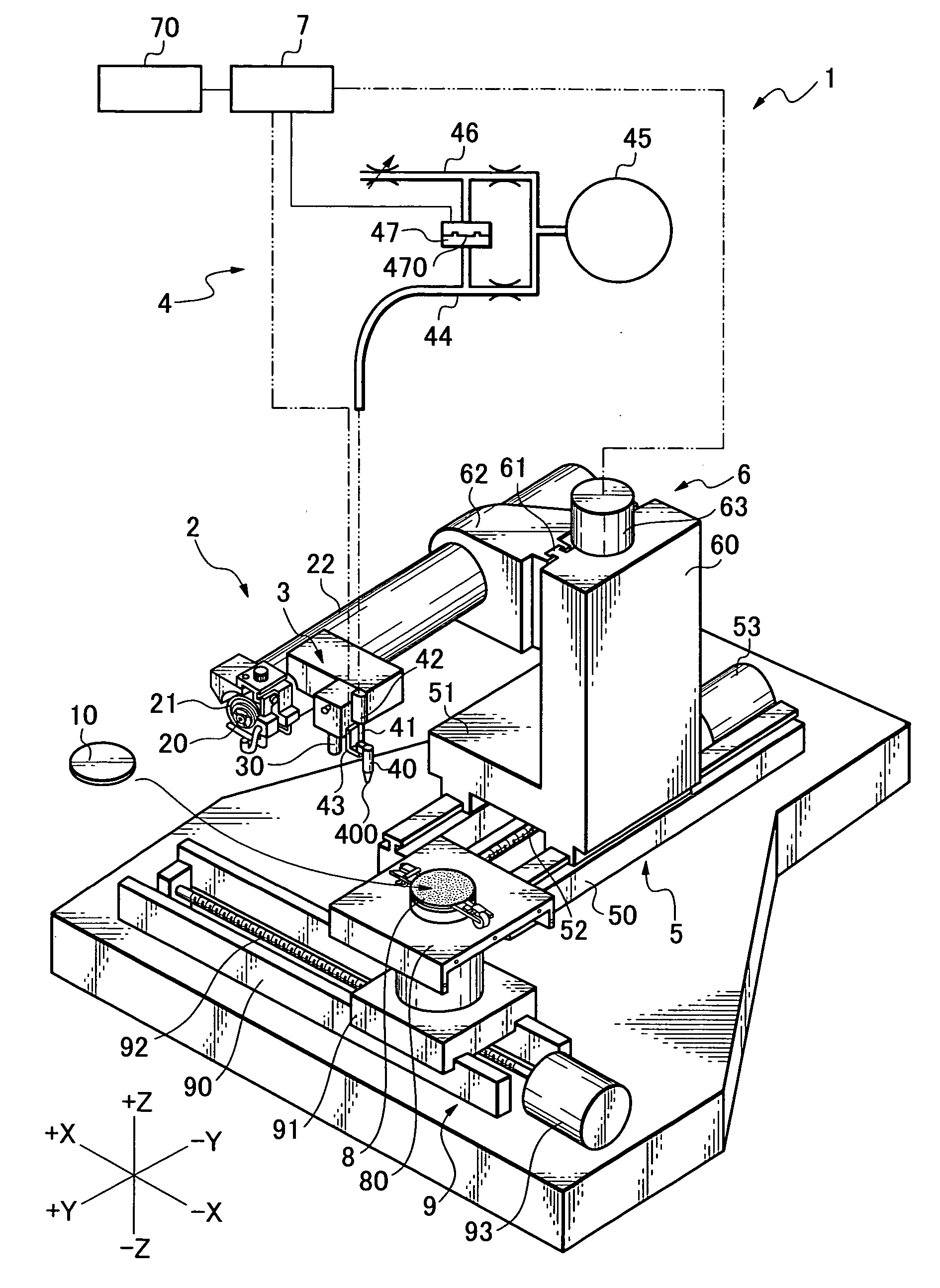
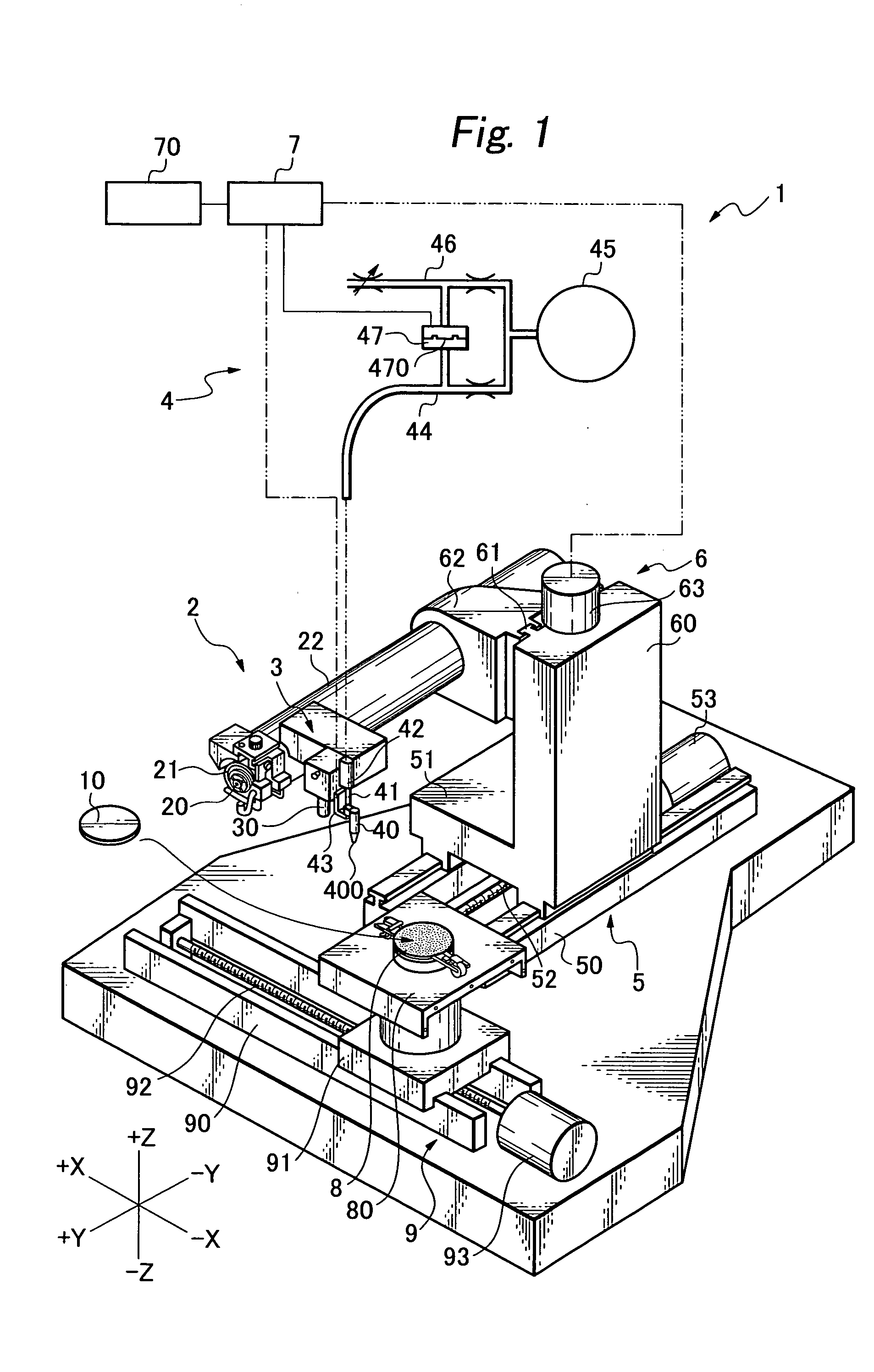
[0025] Processing apparatuses provided with a backpressure sensor include, for example, a cutting apparatus 1 shown in FIG. 1. This cutting apparatus 1 is provided with a cutter 2 including a rotary shaft 20 extending in a Y-axis direction, a rotary blade 21 mounted on a free end portion of the rotary shaft 20, and a spindle housing 22 supporting the rotary shaft 20 rotatably. The cutter 2 is a processing unit for processing an object surface of a workpiece.

[0026] An alignment unit 3 for imaging a specific region of a workpiece, for example, a region to be cut and a cut groove-carrying region by an imaging unit 30, and thereby detecting the specific region is fixed to a side portion of the spindle housing 22. A backpressure sensor 4 for detecting the position of a surface to be processed of a workpiece is fixed to the alignment unit 3, and the backpressure sensor 4 indirectly to the spindle housing 22 via the alignment unit 3. The backpressure sensor 4 may be fixed to the spindle h...


PUM


Abstract

To prevent a blowout nozzle from colliding with a workpiece due to a trouble of a backpressure sensor so as to avoid damage to the workpiece in a processing apparatus provided with a backpressure sensor, the backpressure sensor is formed capable of being freely moved at the blowout nozzle thereof in the air blowout direction and in the direction opposite thereto, and provided with a free-movement detecting sensor adapted to detect an actual free-movement of the blowout nozzle.

Description

BACKGROUND OF THE INVENTION [0001] 1. Field of the Invention [0002] The present invention relates to various kinds of processing apparatuses provided with a backpressure sensor. [0003] 2. Related Art [0004] In order to carry out a processing operation in various kinds of processing apparatuses, it becomes necessary in some cases to detect the position and thickness of a workpiece in advance. [0005] For example, a semiconductor chip utilized in various kinds of electronic devices is formed by dicing with use of a cutting apparatus a semiconductor wafer having a plurality of circuits formed on an outer surface thereof. It has been demanded to form a semiconductor chip thinner in order to reduce the dimensions and weight of an electronic device. In order to meet this demand, a technique called pre-dicing has been put to practical use. [0006] The pre-dicing is a technique for forming in advance grooves in the depth corresponding to the thickness of a final semiconductor chip on an outer...

Claims


Application Information

Patent Timeline
IPC IPC(8): B23D59/00G01B13/00B23Q17/00B28D5/00B28D5/02H01L21/301
CPCB23D59/002B28D5/023B28D5/0094B23Q17/006Y10T83/364
Inventor SHIGEMATSU, KOICHI
Owner DISCO CORP
Why Eureka
Try Eureka