

Fuel delivery systems
a fuel delivery system and fuel technology, applied in the direction of liquid fuel feeders, machines/engines, transportation and packaging, etc., can solve the problems of increasing the limitation of minimizing the diameter of the nozzle, and the increase of the manufacturing cost of the second known fuel delivery system, so as to improve the performance of the jet pump and reduce the associated manufacturing cost
- Summary
- Abstract
- Description
- Claims
- Application Information
AI Technical Summary
Benefits of technology
Problems solved by technology
Method used
Image

Examples
first representative embodiment
[0040] First Representative Embodiment
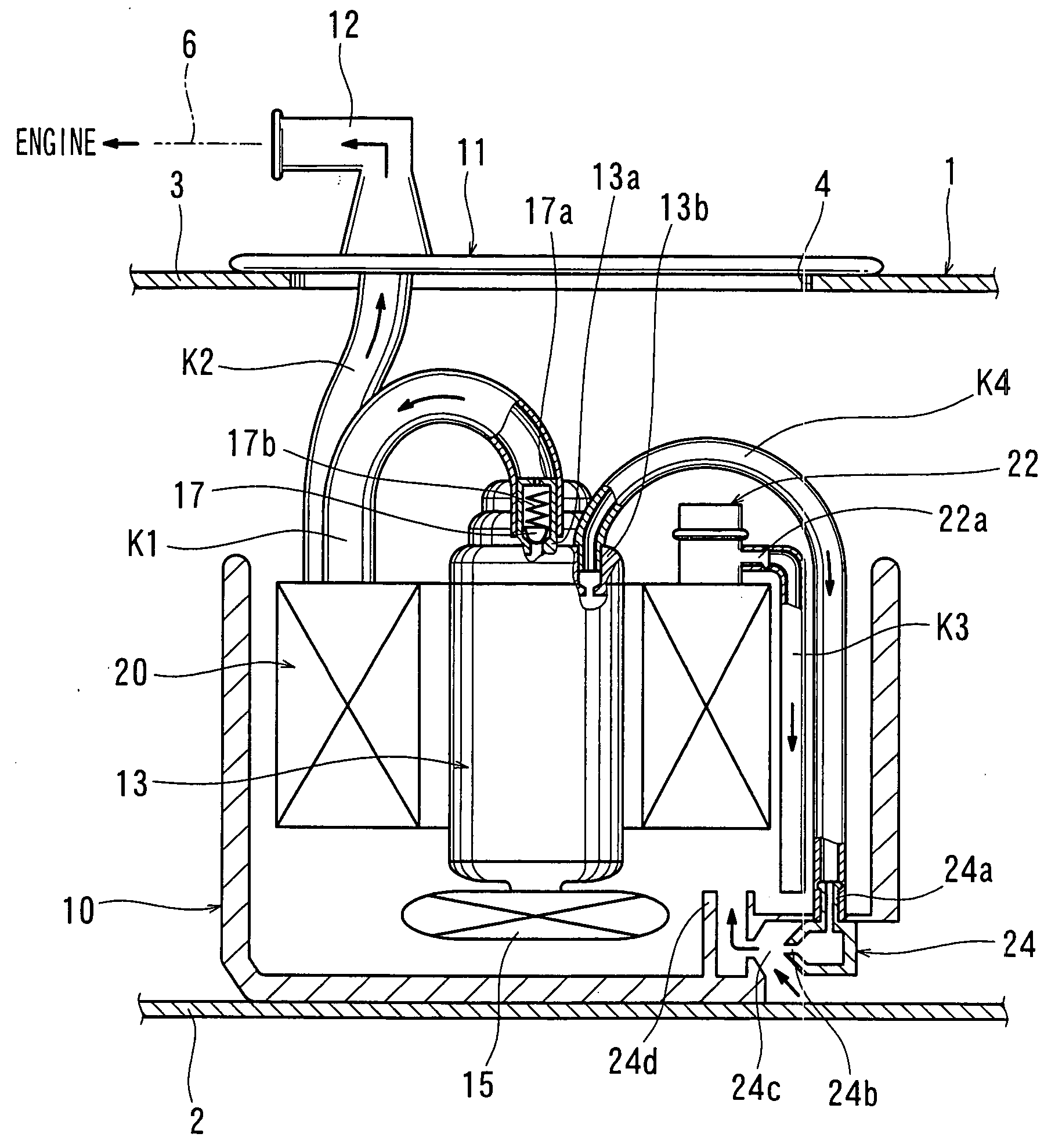
[0041] As shown in FIG. 1, a first representative fuel delivery system generally includes a reservoir 10, a set plate 11, a fuel pump 13, a fuel filter 20, a pressure regulator 22, and a jet pump 24. These elements will be hereinafter described. Here, the first representative fuel delivery system is assembled within a fuel tank 1 that defines a substantially sealed space for storing fuel. The fuel tank 1 has a bottom plate 2 and a top plate 3 with an opening 4. The fuel tank 1 also has a circumferential wall (not shown).
[0042] The reservoir 10 has a substantially cup-shaped configuration and is placed on the bottom plate 2 of the fuel tank 1. The set plate 11 is secured to the upper surface of the top plate 3 of the fuel tank 1 in order to sealingly close the opening 4 of the top plate 3. The set plate 11 has a fuel discharge pipe 12 that communicates between the interior and exterior of the fuel tank 1. On the exterior (outside) of the fuel ta...
second representative embodiment
[0058] Second Representative Embodiment
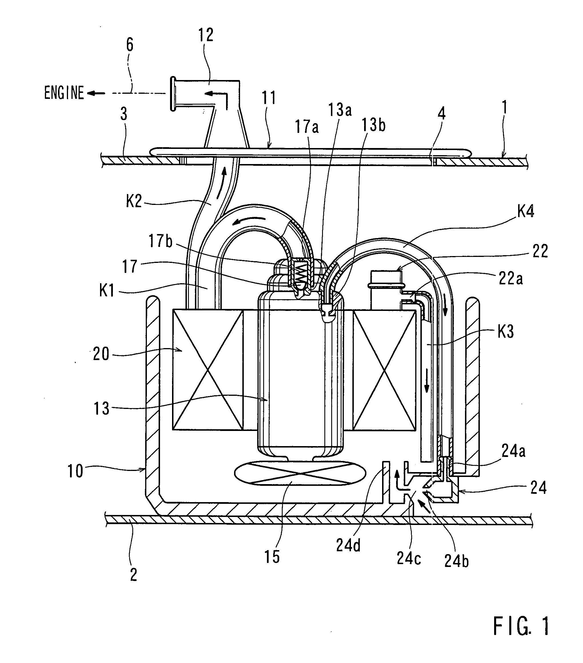
[0059] The second representative fuel delivery system will now be described with reference to FIG. 2. The second representative fuel delivery system is different from the first representative fuel delivery system in that a relief valve 26 is assembled into a flow path. The fourth pipe K4, communicating between the fuel pump 13 and the jet pump 24, configures the flow path. More specifically, as shown in FIG. 2, a substantially T-shaped valve housing 26a is inserted between sections of the fourth pipe K4. The valve housing 26a has two opposing connecting portions joining sections of the fourth pipe K4. The valve housing 26a has a branch pipe 26a1 extending substantially perpendicular to the connecting portions and the branch pipe 26a1 has one end open to the outside of the fourth pipe K4. The relief valve 26 is assembled within the branch pipe 26a1 in order to open and close a flow channel defined within the branch pipe 26a1. A valve spring 26 i...
third representative embodiment
[0062] Third Representative Embodiment
[0063] The third representative fuel delivery system will now be described with reference to FIG. 3. The third representative fuel delivery system is different from the first representative fuel delivery system primarily in that the fuel tank 1 is replaced by a fuel tank 30. Fuel tank 30 has a saddle-shaped configuration. More specifically, the fuel tank 30 has a first tank chamber 31 and a second tank chamber 32 that are delimited by a boundary portion 33. The boundary portion 33 is configured as a raised portion formed within the fuel tank 30 between the bottom plate 31a of the first tank chamber 31 and the bottom plate 32a of the second tank chamber 32. The third representative fuel delivery system is disposed within the first tank chamber 31 in the same manner as in the first representative fuel delivery system. Thus, the bottom plate 31a of the first tank chamber 31 corresponds to the bottom plate 2 of the fuel tank 1 of the first represent...
PUM
 Abstract
Description
Claims
Application Information