
Plasma display module with improved heat dissipation characteristics

a technology of heat dissipation characteristics and plasma display panels, which is applied in the field of plasma display modules, can solve the problems of large amount of heat generated by plasma display panels, low heat transfer effect of heat dissipating members, and even more severe problems of bright latent images, so as to achieve the effect of improving temperature uniformity

Inactive Publication Date: 2005-03-03
SAMSUNG SDI CO LTD
View PDF19 Cites 30 Cited by
  • Summary
  • Abstract
  • Description
  • Claims
  • Application Information

AI Technical Summary

Benefits of technology

[0009] It is therefore an object of the present invention to provide a design for a plasma display module that can provide improved temperature uniformity on a plasma display panel.
[0010] It is further an object of the present invention to provide a design for a plasma display panel where the heat dissipating member can easily be attached to and detached from the plasma display panel.
[0011] It is also an object of the present invention to provide a design for a plasma display module that has an improved heat transfer performance.
[0013] Preferably, the heat dissipating member is made out of a material with a very high thermal conductivity, such as high-orientation graphite. This graphite allows for superb thermal conductivity, especially in a planar direction, thus providing better temperature uniformity across the PDP and reducing or eliminating any temperature gradients across the PDP. The plate structure, preferably made out of a metal like aluminum, is disposed between the graphite and the PDP so the graphite does not directly contact the PDP. This plate structure allows for easy attachment and detachment of the graphite to the PDP, improves temperature uniformity across the PDP, and better draws heat away from the PDP. The plate structure can also be formed between the graphite and the chassis base.

Problems solved by technology

Since the PDM uses a discharge effect for displaying pictures on the plasma display panel, a large amount of heat is generated from the plasma display panel.
One problem with such a design is that the heat transfer effect of the heat dissipating member is low because the materials used for manufacturing the heat dissipating member have a low thermal conductivity coefficient of about 1 W / m·K.
This problem then results in an increase in the discharge strength to achieve a bright image which results in yet more heat generated from the plasma display panel, causing the bright latent image problem to be even more severe.
Also, the local temperature increase in the plasma display panel can generate an internal heat stress that can cause a crack of the plasma display panel which is usually made of glass.
However, the heat transfer performance in Morita '374 is still not sufficient because of pores generated in the heat dissipating member when attaching the heat dissipating member between the plasma display panel and the chassis base.
Also, the high conductivity heat dissipating member is hard to attach to and detach from the plasma display panel.

Method used


Image

  • Plasma display module with improved heat dissipation characteristics
  • Plasma display module with improved heat dissipation characteristics
  • Plasma display module with improved heat dissipation characteristics

Examples


Embodiment Construction

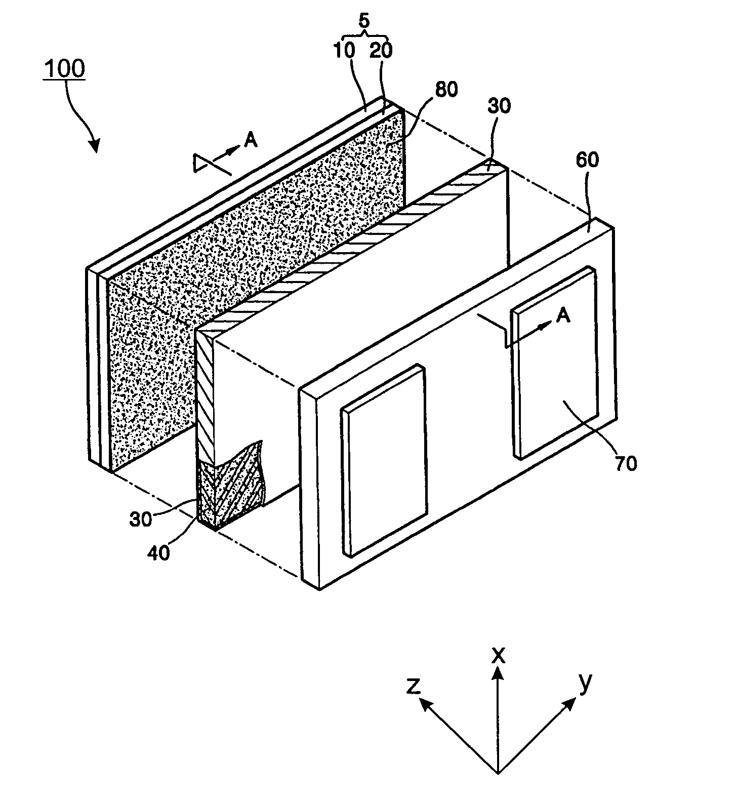
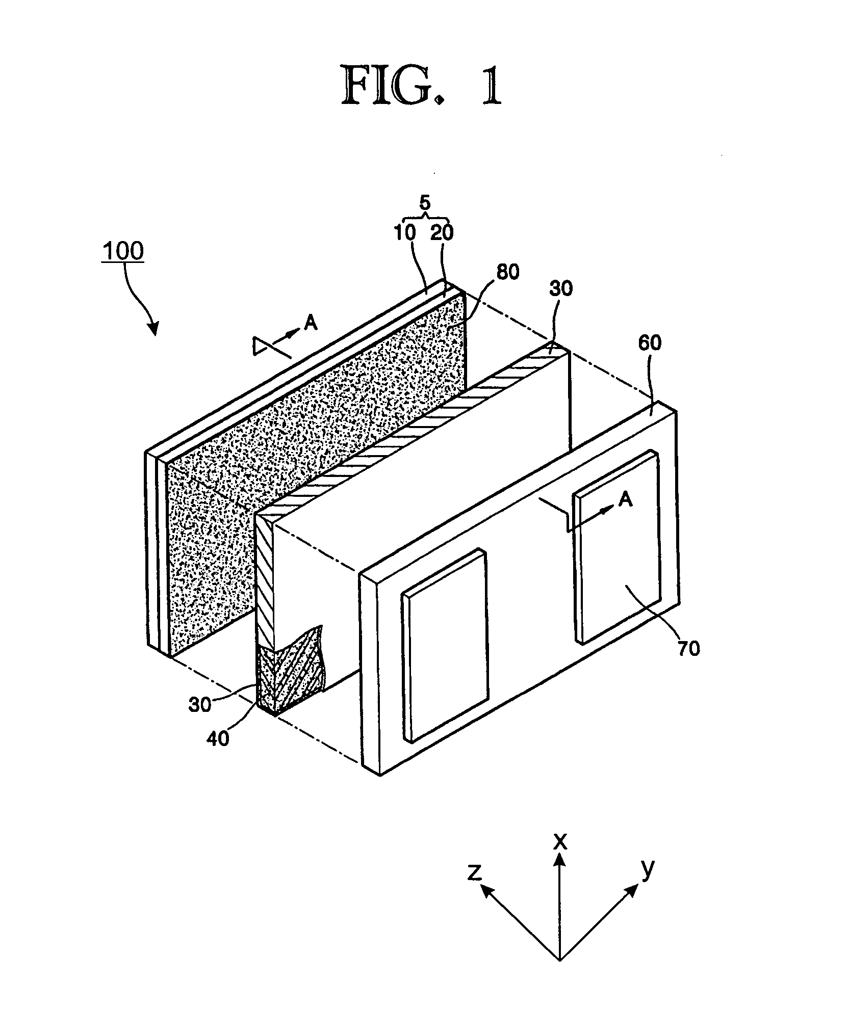
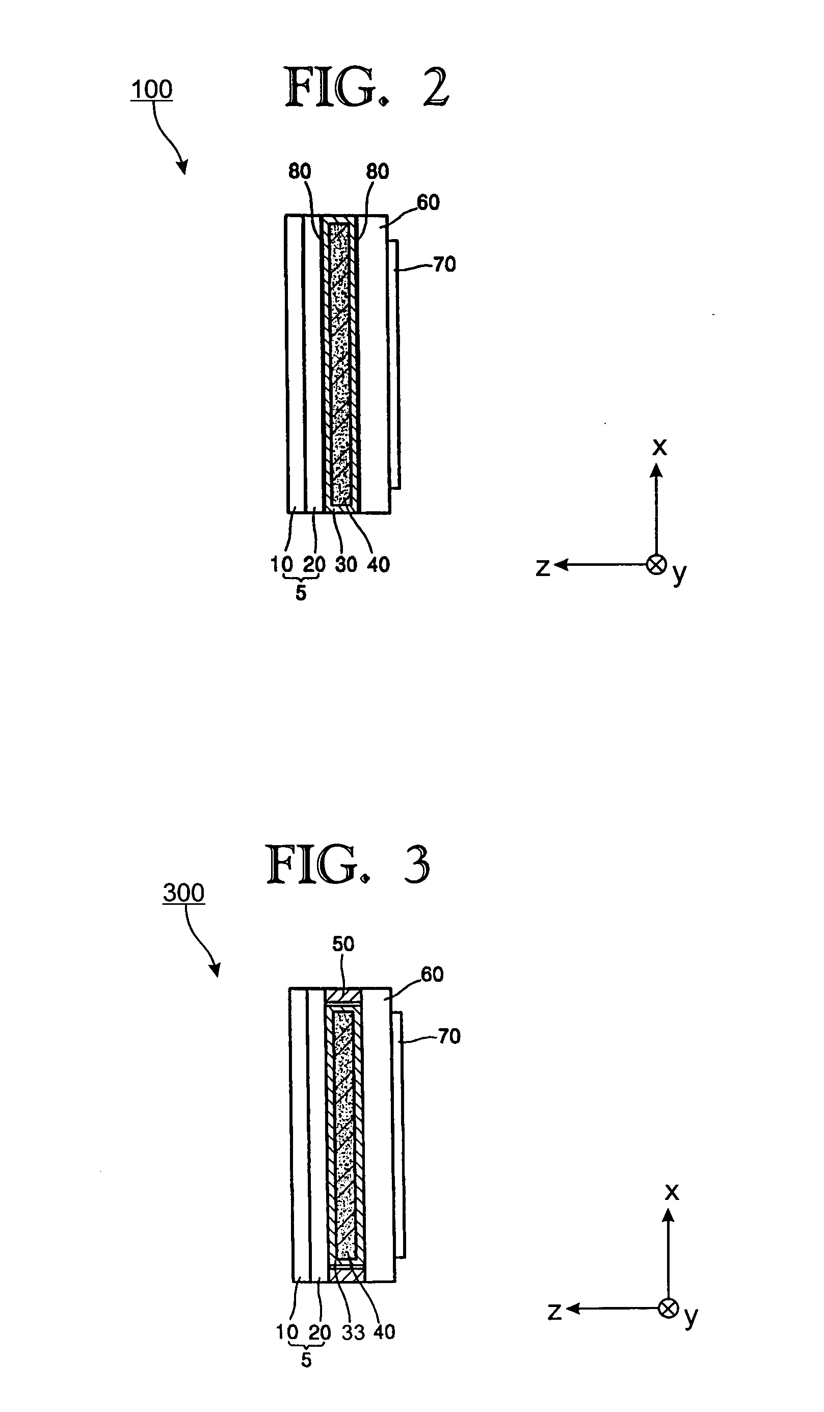
[0023]FIG. 1 is an exploded perspective view of a plasma display module (PDM) 100 according to an embodiment of the present invention, and FIG. 2 is a cross-sectional view of the PDM 100 taken along line A-A in FIG. 1. Turning now to FIGS. 1 and 2, the plasma display module 100 includes a plasma display panel (or PDP) 5, a chassis base 60, a circuit board 70, and a heat dissipating member 40 and a plate structure 30. The heat dissipating member 40 and the plate structure 30 are disposed between the PDP 5 and the chassis base 60. The PDP 5 is made up of a front panel 10 and a rear panel 20. The PDP 5 is generally formed of glass and represents the image display section of PDM 100 that displays images via plasma discharge.

[0024] The chassis base 60 performs as a heat sink for promoting heat transfer from the PDM 5 and from the circuit board 70. Chassis base 60 is preferably made of a material having a superior thermal conductivity, such as aluminum. A circuit board 70 is disposed on ...


PUM


Abstract

Provided are designs for a plasma display module (PDM) that has a plasma display panel (PDP) and a chassis base with circuits mounted thereon. Heat dissipating layers and plane structures are formed between the PDP and the chassis base. The heat dissipating layer and the plane structure have novel shapes and sizes and are made out of specific materials or combinations of materials to improve the heat dissipating characteristics for the PDM. Preferably, a high-orientation graphite material having a high thermal conductivity is used for the heat dissipating layer. The plane structure is a highly conductive metal that is positioned between the graphite layer and the glass PDP to form a better contact to the PDP, to better draw heat away from the PDP and to allow for easy attachment and detachment of the graphite layer to the PDP.

Description

CLAIM OF PRIORITY [0001] This application makes reference to, incorporates the same herein, and claims all benefits accruing under 35 U.S.C. §119 from an application for PLASMA DISPLAY MODULE earlier filed in the Korean Intellectual Property Office on 1 Sep. 2003 and there duly assigned Serial No. 2003-60744. BACKGROUND OF THE INVENTION [0002] 1. Field of the Invention [0003] The present invention relates to a plasma display module, and more particularly, to a structurally improved plasma display module that has a uniform temperature distribution profile and a higher heat transfer efficiency. [0004] 2. Description of the Related Art [0005] A plasma display module (PDM) is a flat panel display device for displaying pictures by using a discharge effect. Because of its very good performances and characteristics such as high display capacity, brightness, contrast, latent image, viewing angle, and thin and large screen size, the PDM is considered to be one of the next generation display ...

Claims


Application Information

Patent Timeline
IPC IPC(8): H01J17/49G09F9/313G09G3/28H01J17/28
CPCH05K7/20963H01J11/10H01J17/16H01J17/28H04N5/645
Inventor KIM, SOK-SANCHO, IN-SOOKIM, KI-JUNGKANG, TAE-KYOUNG
Owner SAMSUNG SDI CO LTD
Learn More