Apparatus and method for ink-jet printing onto an intermediate drum in a helical pattern

a technology of inkjet printing and drums, applied in the direction of printing mechanisms, spacing mechanisms, printing, etc., can solve the problems of undesired defects, waste of time upon the advancement of the medium and the return of the drum, and waste of tim

Inactive Publication Date: 2005-03-03
FUNAI ELECTRIC CO LTD
View PDF26 Cites 70 Cited by
  • Summary
  • Abstract
  • Description
  • Claims
  • Application Information

AI Technical Summary

Benefits of technology

[0016] A further object of the present invention is to provide the above method and apparatus for helical drum printing that has a high print quality and a high throughput in an ink-jet printer.
[0021] In accordance with further embodiments of the present invention, the method of helical ink-jet drum printing adjusts the timing of the plurality of nozzles to compensate for the aliasing created by the shearing algorithm.
[0026] In accordance with further embodiments of the present invention, the controller in the ink-jet drum printer causes a medium to rotate prior to applying the medium to a drum to transfer the deposited ink thereto, and controls the timing of the plurality of nozzles to correct for aliasing created by the shearing algorithm.
[0030] Objects and advantages of the present invention are accomplished, as noted above, by preferred embodiments using a plurality of ink-jet print heads to place an image on an intermediate drum, impervious to ink, in a helical pattern. To compensate for helical printing the image is altered by software manipulation and nozzle timing adjustment. The plurality of print heads move parallel to the axis of rotation of the drum while the drum is simultaneously rotating causing the image to be placed in a helical pattern. Once the entire image is placed on the drum, paper or another medium is rolled against the drum under pressure and the image is transferred to the paper. Helical ink-jet printing produces skewing and aliasing problems. The skewing has been corrected for by modifying the image before it is printed. By inverse shearing, through a shear algorithm, the image skew produced by the helical printing can be eliminated.
[0032] In accordance with preferred embodiments of the present invention as noted above, the ink-jet printer has a plurality of fixed print heads which helically deposit ink across a drum. With this arrangement, an additional problem is encountered in that each nozzle on the plurality of print heads is vertically aligned at a different angle relative to the drum. If uncorrected, this would result in printing distortions. The present invention corrects for these different alignments by accurately arranging the nozzle columns to fire the nozzles in a proper order.

Problems solved by technology

However, time is wasted upon the advancement of the medium and returning the print head to the starting position.
This wasted time represents a lower potential throughput.
In addition, an objectionable vibration is generated upon returning of the carriage and advancing of the medium, thus generating undesired defects in the resultant printed medium.
However, the cost of such printers for many business and most home users is too expensive.
Printing in a helical pattern, however, presents impediments to high image quality.
Aliasing shows up as jagged lines that can be objectionable, and is most noticeable on horizontal lines.
While Davis et al. discloses printing in a helical pattern, Davis et al. does not resolve the problem of image skew resulting from helical printing.
This results in wasted time for advancing the printhead, and unfavorable vibration due to the starting and stopping of the printhead upon advancement.
Additionally, the use of a ink-jet print head creates additional problems of nozzle placement and selection which are unrelated to the light scanning method of Morizumi et al.

Method used


Image

  • Apparatus and method for ink-jet printing onto an intermediate drum in a helical pattern
  • Apparatus and method for ink-jet printing onto an intermediate drum in a helical pattern
  • Apparatus and method for ink-jet printing onto an intermediate drum in a helical pattern

Examples


second embodiment

[0081] If the resulting print quality as described above in the first preferred embodiment is not acceptable, then a second preferred embodiment can encompass the properties of the first preferred embodiment, but additionally correct for aliasing generated from the skew correction. In the second embodiment, the image is rotated on the drum, the medium is rotated correspondingly, a shearing algorithm is performed, and a timing of the nozzles is modified, as explained below.

[0082] Rotate Image

[0083] In particular, the image is rotated on the drum 10 using a different shear correction on the original image 50 as shown in FIG. 11. The image bottom is moved to the left with respect to the top, resulting in a proper rectangular image. The image 60 on the drum is rotated from the original image 50, so that horizontal lines are now completely free from aliasing errors. That is, a single nozzle from the column of nozzles 41 is used to define the top or bottom of any horizontal element in th...

third embodiment

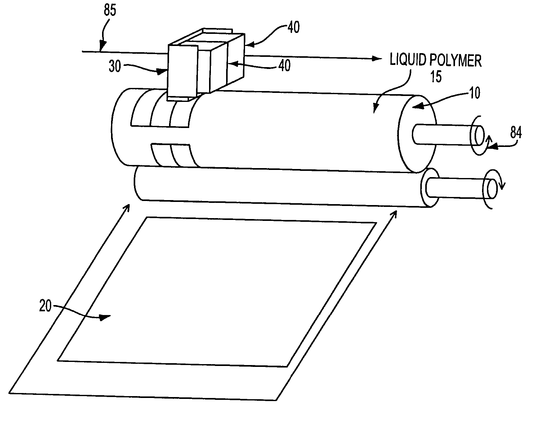
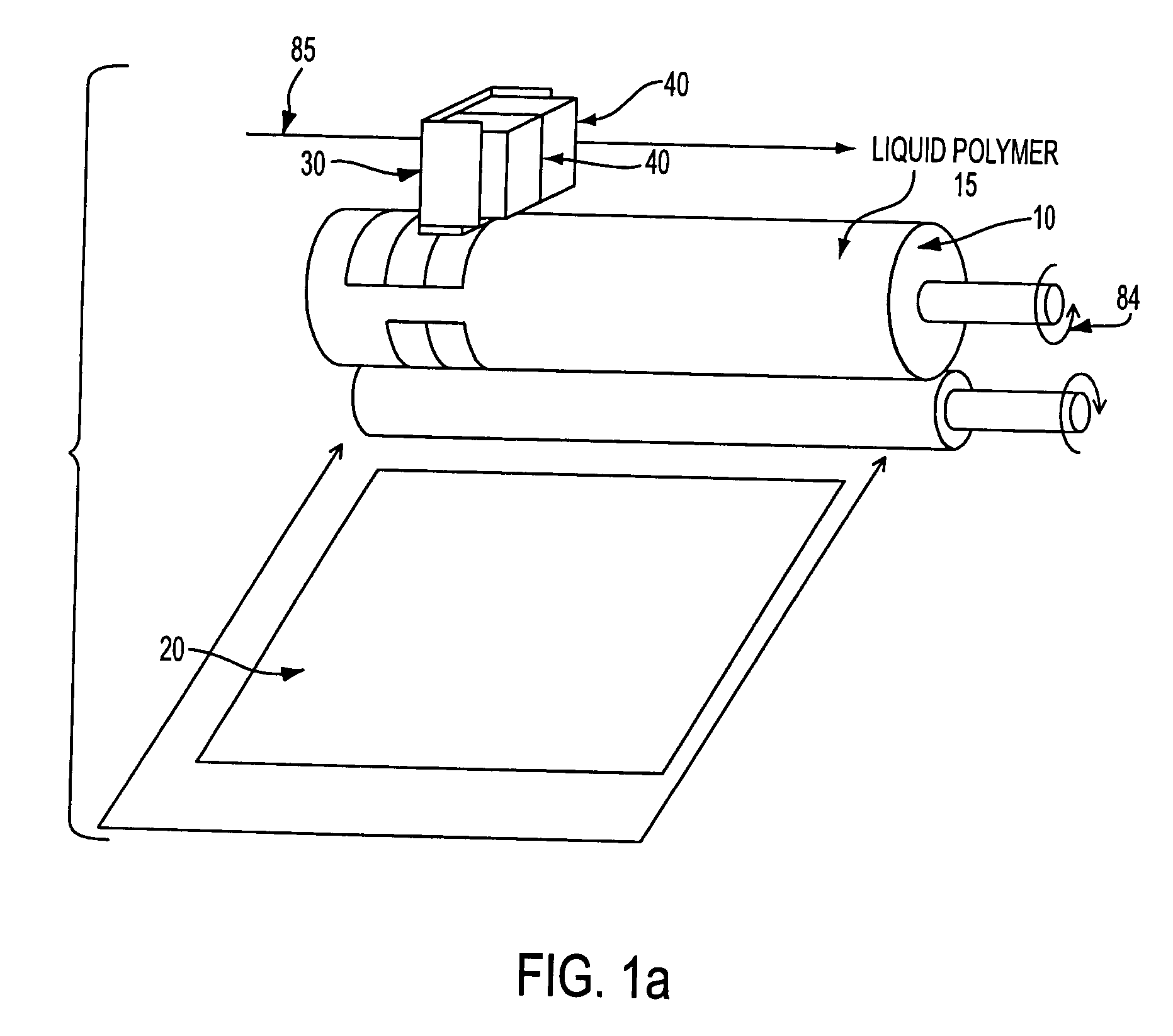
[0102] In a third preferred embodiment, apparatus and method of the first and second preferred embodiments are controlled in view of a high resolution rotary tachometer. The third embodiment employs a high resolution rotary tachometer for drum 10. The resolution of the printing system is optimally equal to the print resolution determined by distance Z or an integer factor different, so that the print resolution can be easily created from the tachometer information. The print head timing information is then derived from the tachometer data. The drum 10 rotates at a uniform rate during the entire process. An optical grating and sensor (or equivalent) tracks the carriage travel along carriage path 85 of drum 10, with the resolution closely related to the vertical resolution determined by distance X.

[0103] The carriage movement control system uses the drum tachometer and vertical grating sensor to achieve the correct carriage movement along carriage path 85, and horizontal versus vertic...


PUM


Abstract

An apparatus and method for ink-jet printing onto an intermediate drum in a helical pattern while correcting for image skew and aliasing. A plurality of ink-jet print heads place an image on an intermediate drum, impervious to ink, in a helical patter. To compensate for helical printing, the image is altered by nozzle placement and image manipulation to correct for skewing errors, and thereafter, the nozzle timing is adjusted to correct for aliasing. The plurality of print heads move parallel to the axis of rotation of the drum while the drum is simultaneously rotating, causing the image to be placed in a helical pattern. Once the entire image is placed on the drum, paper is rolled against the drum under pressure and the image is transferred thereto.

Description

BACKGROUND OF THE INVENTION [0001] 1. Field of the Invention [0002] The present invention relates to a system and method for printing an image onto a drum and transferring the printed image from the drum onto a medium. More particularly, the present invention relates to an ink-jet printer with large throughput where an image is printed onto a drum in a helical manner while compensating for skewing and aliasing caused by the helical printing. [0003] 2. Description of the Related Art [0004] Ink-jet printers typically use a carriage to move a print head across a medium, such as paper, and to print onto the medium in swaths of defined widths. After each printing pass, the carriage returns the print head to a starting position to begin the next pass, after which the medium is advanced an additional swath width. Eventually, the entire medium is printed onto by the print head. However, time is wasted upon the advancement of the medium and returning the print head to the starting position. ...

Claims


Application Information

Patent Timeline
Patent Type & Authority Applications(United States)
IPC IPC(8): B41J2/005B41J2/045
CPCB41J2/0057B41J2/04505B41J2/0451B41J19/16B41J2/04573B41J2/0458B41J2/04543
Inventor ASKREN, BENJAMIN A.BURDICK, ROBERT L.CHAPPEL, BILL C.CHEE, CHRISTOPHER G.COOK, WILLIAM P.CSELEDY, DAVID M.FOSTER, LARRY S.HARDEN, JAMES P.KLEIN, WILLIAM S.
Owner FUNAI ELECTRIC CO LTD
Why Eureka
Try Eureka