Simultaneous phase-shifting fizeau interferometer

a phase-shifting fizeau interferometer and phase-shifting technology, applied in the field of electromagnetic wavefront measurement, can solve the problems of significant background light that may affect the measurement, difficult and expensive implementation, and inability to properly encode, so as to reduce measurement integration time and mitigate reflections

Active Publication Date: 2005-03-03
ONTO INNOVATION INC
View PDF7 Cites 48 Cited by
  • Summary
  • Abstract
  • Description
  • Claims
  • Application Information

AI Technical Summary

Benefits of technology

[0010] Alternatively, two beams with orthogonal polarization are injected into the Fizeau cavity at different angles, such that after reflection from the reference and test optics they are substantially collinear. Unwanted reflections are blocked at the focal plane through the use of a circular aperture. Short coherence length light and a delay line may be used, as taught by Kuchel et al., to mitigate stray reflections, reduce measurement integration times, and implement temporal phase averaging.

Problems solved by technology

One of the problems identified in the prior art has been the ability to properly encode the reference and test beams in the measurement portion of a Fizeau-type interferometer.
Thus, the Kuchel et al. approach requires fine adjustment of the length of the delay path, which is difficult and expensive to implement.
In addition, the presence of the two incoherent light beams produces significant background light that may affect the measurements.

Method used


Image

  • Simultaneous phase-shifting fizeau interferometer
  • Simultaneous phase-shifting fizeau interferometer
  • Simultaneous phase-shifting fizeau interferometer

Examples


embodiment 38

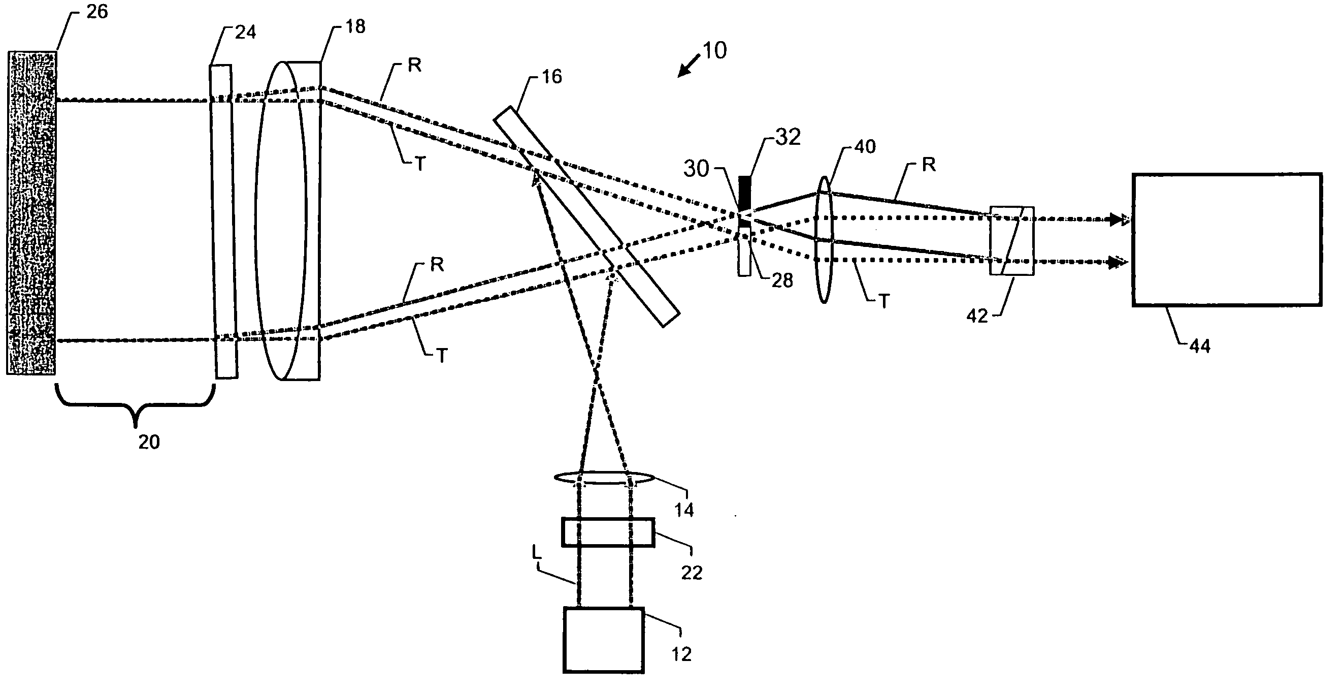
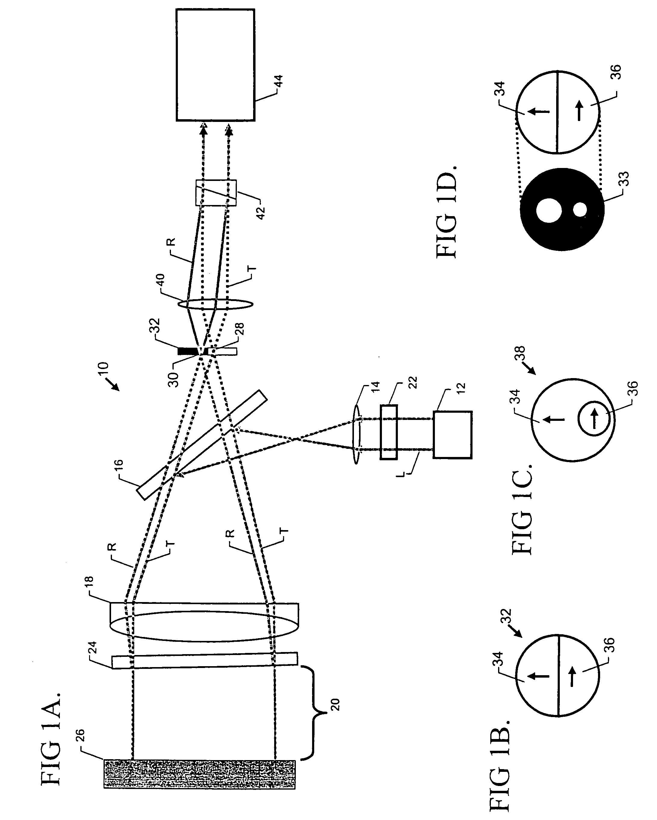
[0029] According to the invention, a spatial polarization filter 32 is placed at the focal plane of the collimation lens 18. As illustrated in FIG. 1B, the polarization filter 32 includes two regions with different polarization components (preferably orthogonal to each other) positioned such that the test beam T and the reference beam R are transmitted through the different regions. Thus, as a result of interaction with the polarization elements, each beam emerges with orthogonal polarization. In the embodiment of FIG. 1B, the polarization filter 32 consists of a first linear-polarizer region 34 and a second linear-polarizer region 36 that abut each other and have axes of polarization oriented orthogonally with respect to each other. In another embodiment 38, shown in FIG. 1C, the second polarizer region 36 is completely circumscribed by the first polarizer region 34. Such a device can be manufactured, for example, as a patterned polarizer (available from Codixx of Barleben, Germany...

embodiment 54

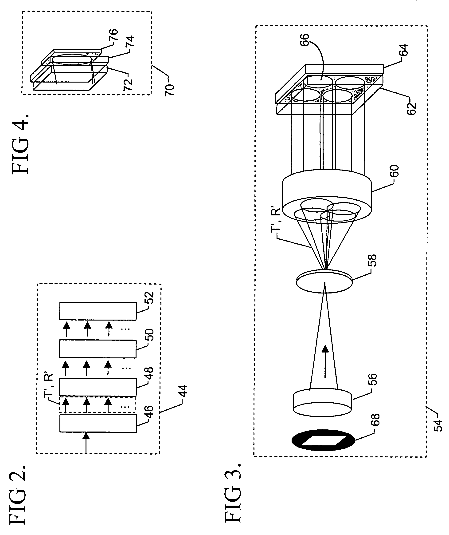
[0032] As described in copending U.S. Ser. No. 10 / 652,903, hereby incorporated by reference, spatial phase-shifting interferometer module 44 suitable for the invention can be implemented in various arrangements. For example, FIG. 3 illustrates an embodiment 54 wherein the orthogonally polarized reference and test beams are focused by a lens 56 onto an appropriately positioned beamsplitter element 58. The beamsplitter, through reflective, refractive or diffractive elements, produces a plurality of sub-image beam pairs (reference plus test) which are collimated and imaged by a lens 60 through a phase interference plate 62 onto a detector 64. The plate 60 phase shifts and appropriately overlaps the collimated sub-image beams, thereby delivering phase-shifted interferograms 66 on the detector 64. The plate 62 comprises substantially planar birefringent waveplates and polarizing elements arranged in parallel and / or adjoining layers, as is known in the art.

[0033] The entrance region of th...

embodiment 70

[0034] In another embodiment 70 shown in FIG. 4, the spatial phase-shifting interferometer employs a spatial-frequency carrier method of detecting the phase variations in the test wavefront. The reference and test beams are collimated as described above and directed to a polarization element 72 (which may be a birefringent crystal, such as a Wollaston prism, or any other refractive or diffractive component) inside the interferometer 70. The element 72 acts as a polarization beamsplitter, thus introducing an angular separation between corresponding wavefronts. The waves are then interfered by a polarizer 74 and imaged on a single detector 76. The contrast of the corresponding interferograms can be adjusted by rotating the polarizer 74 to compensate for arbitrary polarizations of the imaged reference and test waves. The digitized interferograms are further processed by computer to calculate phase and characterize the test surface.

[0035] In another embodiment 80 of the invention illust...


PUM


Abstract

The tilted relationship between the reference and test mirrors of a Fizeau interferometer is used to spatially separate the reflections from the two surfaces. The separate beams are filtered through a spatial polarization element that provides different states of polarization to the beams. The beams are subsequently recombined to form a substantially collinear beam that is processed using a spatial-phase-shift interferometer that permits quantitative phase measurement in a single video frame. Alternatively, two beams with orthogonal polarization are injected into the Fizeau cavity at different angles, such that after reflection from the reference and test optics they are substantially collinear. Unwanted reflections are blocked at the focal plane through the use of a circular aperture. Short coherence length light and a delay line may be used to mitigate stray reflections, reduce measurement integration times, and implement temporal phase averaging.

Description

RELATED APPLICATIONS [0001] This application is based on and claims the priority of U.S. Provisional Application Ser. No. 60 / 498,522, filed Aug. 28, 2003.BACKGROUND OF THE INVENTION [0002] 1. Field of the Invention [0003] The invention relates to measurement of electromagnetic wavefronts. In particular, it pertains to quantitative, instantaneous measurement of interference light beams produced by a Fizeau interferometer. [0004] 2. Description of the Related Art [0005] Light-beam measurements and characterization are important in the manufacture of many optical components, such as data-storage laser heads, for example. Accordingly, many optical interferometric systems have been devised to increase the accuracy and reliability of the measurements. In general, a front-end interferometric device that produces a test and a reference beam is combined with a back-end optical device for resolving phase differences between the beams. This may be achieved simultaneously by encoding (or “marki...

Claims


Application Information

Patent Timeline
Patent Type & Authority Applications(United States)
IPC IPC(8): G01B9/02G01B11/30
CPCG01B11/303G01B9/02003G01B9/02057G01B2290/45G01B2290/70G01B2290/50G01B9/02091
Inventor MILLERD, JAMES E.WYANT, JAMES C.
Owner ONTO INNOVATION INC
Why Eureka
Try Eureka