Efficient optical parametric oscillator with photon recycling

a technology of optical parametric oscillators and photon recycling, applied in the direction of instruments, laser details, light demodulation, etc., can solve the problems of buildup of idler power with each successive parametric process, and achieve the effect of effectively building up parametric processes and double process efficiency

Active Publication Date: 2005-03-03
BAE SYST INFORMATION & ELECTRONICS SYST INTERGRATION INC
View PDF2 Cites 6 Cited by
  • Summary
  • Abstract
  • Description
  • Claims
  • Application Information

AI Technical Summary

Benefits of technology

[0015] One therefore takes advantage of a common idler field to effectively buildup the parametric processes in the other cascaded optical parametric oscillators. Thus the location of the optical parametric oscillators in a single cavity tuned to the longer wavelength, in this case the idler wavelength, permits recapture of unused signal photons. This in one embodiment, can double the efficiency of the process.

Problems solved by technology

The result is a buildup of idler power with each successive parametric process.

Method used


Image

  • Efficient optical parametric oscillator with photon recycling
  • Efficient optical parametric oscillator with photon recycling

Examples


Embodiment Construction

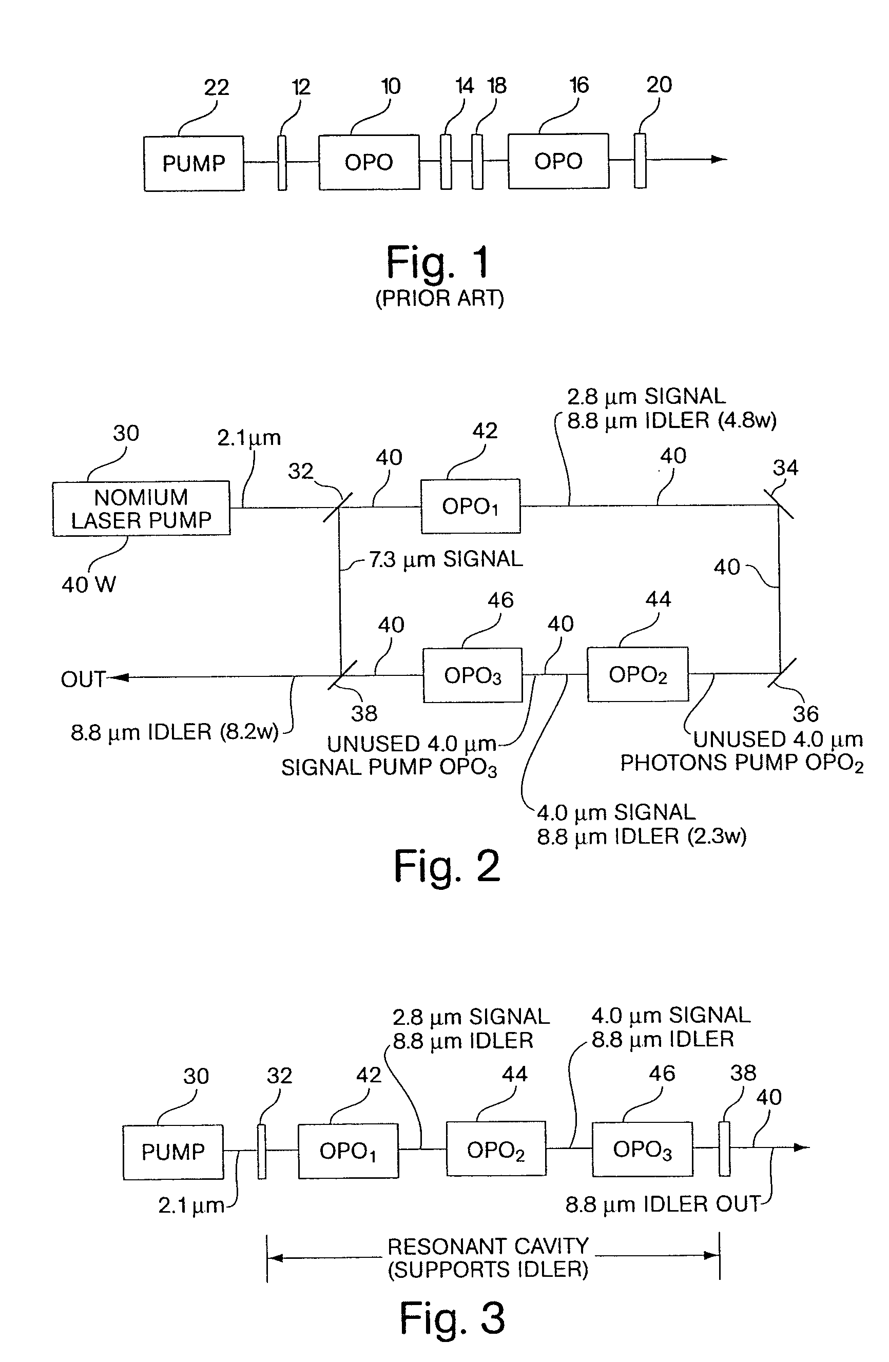
[0025] Referring now to FIG. 1, in a prior art tandem optical parametric oscillator configuration, a first optical parametric oscillator 10 is located in a cavity bounded by mirrors 12 and 14, whereas a second parametric oscillator 16 is located in the cavity bounded by mirrors 18 and 20. The first of the tandem optical parametric oscillators is pumped by a pump 22, with the output of the optical parametric oscillator 10 pumping optical parametric oscillator 16.

[0026] The system in FIG. 1 while capable of converting pump wavelengths into longer wavelengths, results in an overall efficiency of no greater than 10%. This means that if the pumping power is 40-W, the output power for the tandem system is only 4-W.

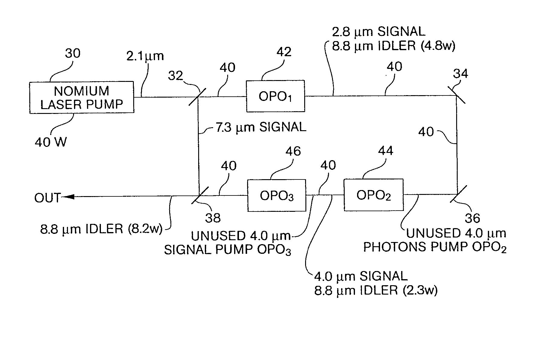
[0027] Referring to FIG. 2, unused signal photons may be reintroduced to pump follow-on optical parametric oscillators as will be described.

[0028] In this figure a Holmium pump laser 30 produces a 2.1 μm 40-W output coupled into a ring cavity defined by mirrors 32, 34, 36 and...


PUM

PropertyMeasurementUnit
idler wavelengthaaaaaaaaaa
pump wavelengthaaaaaaaaaa
wavelengthaaaaaaaaaa

Abstract

The problem of the low efficiency of large quantum defect optical parametric oscillators is solved by recycling unused photons in a process involving pumping additional parametric processes having a common resonant wavelength. In order to improve the efficiency, a series of optical parametric oscillators are pumped with unused signal photons which exist at the output of a previous optical parametric oscillator that generates both signal and idler outputs, with the idler constituting the desired output. In one embodiment, a Holmium pump laser at 40-W produces a 2.1 μm output which is used to pump a first optical parametric oscillator that is non-linear and has a large phase match range crystal, namely ZGP. The output from the first optical parametric oscillator is a 2.8 μm signal and the desired 8.8 μm idler comes out at 4.8-W. The output from the first optical parametric oscillator pumps the second optical parametric oscillator with the unused 2.8 μm signal photons, with the resultant output from the second optical parametric oscillator being a 4.0 μm signal and the 8.8 μm idler at an additional 2.3-W. The 4.0 μm signal pumps the third optical parametric oscillator so as to produce a 7.3 μm signal and the 8.8 μm idler which comes out at an additional 1.1-W. As a result, the combined output power of the idler totals 8.2-W, for an overall efficiency of 20%.

Description

FIELD OF INVENTION [0001] This invention relates to efficient pumping of optical parametric oscillators and more particularly to the provision of a system which locates a number of optical parametric oscillators in a cavity, with photon recycling used to increase pumping efficiency. BACKGROUND OF THE INVENTION [0002] It has long been desired to develop a long wave infrared source which is also solid state. Applications for such long wave lasers include infrared countermeasures, and targeting systems as well as biochemical detection using laser spectroscopy. In order to provide long wave infrared radiation, one starts at a moderately short wavelength of about 2 microns. It is then necessary to be able to convert the 2 micron pumping energy to the 8 to 12 micron band. [0003] Intrinsically this is not a very efficient process because one is starting with 2 micron photons and trying to obtain 8 microns. As a result there is a very large quantum defect, relating to the difference in wave...

Claims


Application Information

Patent Timeline
Patent Type & Authority Applications(United States)
IPC IPC(8): G02FG02F1/39H01S3/109
CPCG02F2201/16G02F1/39
Inventor SNELL, KEVIN J.
Owner BAE SYST INFORMATION & ELECTRONICS SYST INTERGRATION INC
Why Eureka
Try Eureka