
Optical elements and methods for making thereof

a technology of optical elements and fabrication methods, applied in the field of optical elements, can solve the problems of unstable, unstable, uneconomical techniques, etc., and achieve the effect of unique optical properties and precise control of optical properties

Inactive Publication Date: 2005-03-03
ESSILOR INT CIE GEN DOPTIQUE +1
View PDF28 Cites 83 Cited by
  • Summary
  • Abstract
  • Description
  • Claims
  • Application Information

AI Technical Summary

Benefits of technology

[0009] Preferred methods provide exceptionally precise control over optical properties as a function of position within the optical element, and thus provide optical elements having unique optical properties. Preferred optical elements include lenses that can correct relatively complicated or higher order aberrations that may cause vision problems.

Problems solved by technology

However, lenses made by these fabrication techniques are only capable of correcting relatively simple vision problems.
Other fabrication techniques have been developed to address more complex vision problems, but these techniques are uneconomical because they are relatively complicated and not well-suited for mass production.
However, the presence of unreacted photoreactive substances remaining within the irradiated article often presents stability problems.
However, such methods seek to control optical properties by controlling the thickness of the lens, rather than by controlling the refractive index of the material from which the lens is made.

Method used


Image

  • Optical elements and methods for making thereof
  • Optical elements and methods for making thereof
  • Optical elements and methods for making thereof

Examples


example 1

[0081] A kit having Parts I and II was made by intermixing the following ingredients:

[0082] Part I (high index): 23.0 g of reactive Bisphenol A glycerolate (1 glycerol / phenol) diacrylate (BPGDA, nD=1.557), 46.0 g of ethanol, 0.23 g of photoinitiator (Irgacure 184).

[0083] Part II (low index): 25.0 g of reactive 2-hydroxy ethyl methacrylate (HEMA, nD=1.453), 25.0 g of ethanol, 0.25 g of photoinitiator (Irgacure 184).

examples 2-7

[0084] A series of polymerizable compositions were prepared by intermixing the relative amounts (weight basis) of Parts I and II of the kit of Example 1 as shown in Table 1. Table 1 also shows the refractive indices (nD) of each polymerizable composition and the corresponding refractive indices of the polymers obtained by UV-curing each of the polymerizable compositions.

TABLE 1CompositionNo.Part II (%)Part I (%)nD (uncured)nD (cured)201001.4171.558320801.4131.535440601.4111.516560401.4071.504680201.4051.483710001.4041.474

example 8

[0085] A kit having Parts I and II was made by intermixing the following ingredients:

[0086] Part I (low index): 50.0 g of reactive tri(propylene glycol) diacrylate (TPGDA, nD=0.450), 50.0 g of ethanol, 0.51 g of photoinitiator, Irgacure 184, and 0.52 g of azoisobutyronitrile (AIBN).

[0087] Part II (high index): 162.8 g of reactive Bisphenol A glycerolate (1 glycerol / phenol) diacrylate (BPGDA, nD=1.557), 162.8 g of ethanol, 1.63 g of photoinitiator, Irgacure 184, and 1.63 g of thermal initiator, azoisobutyronitrile (AIBN).


PUM

PropertyMeasurementUnit
Poweraaaaaaaaaa
Compositionaaaaaaaaaa
Ratioaaaaaaaaaa

Abstract

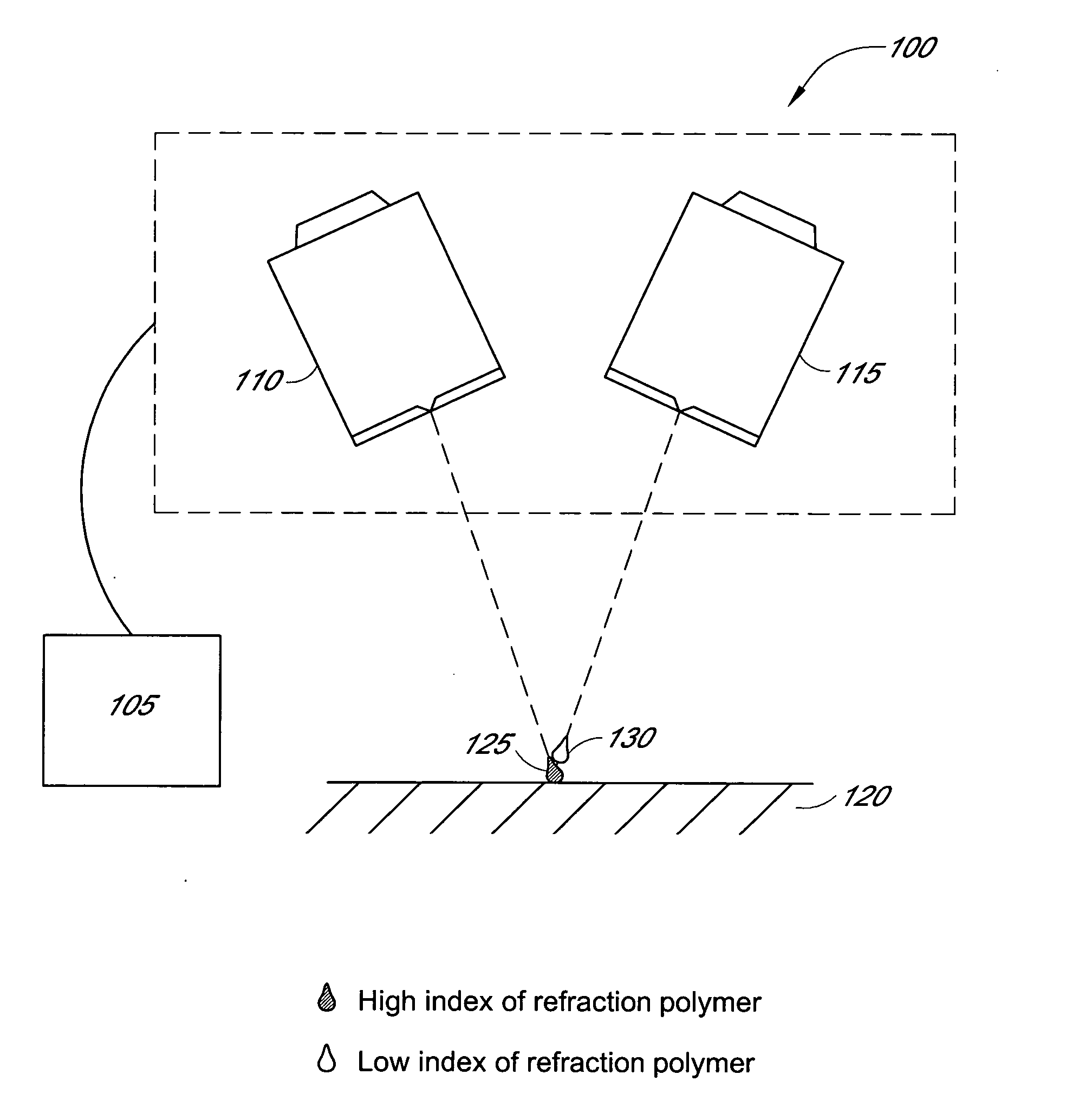
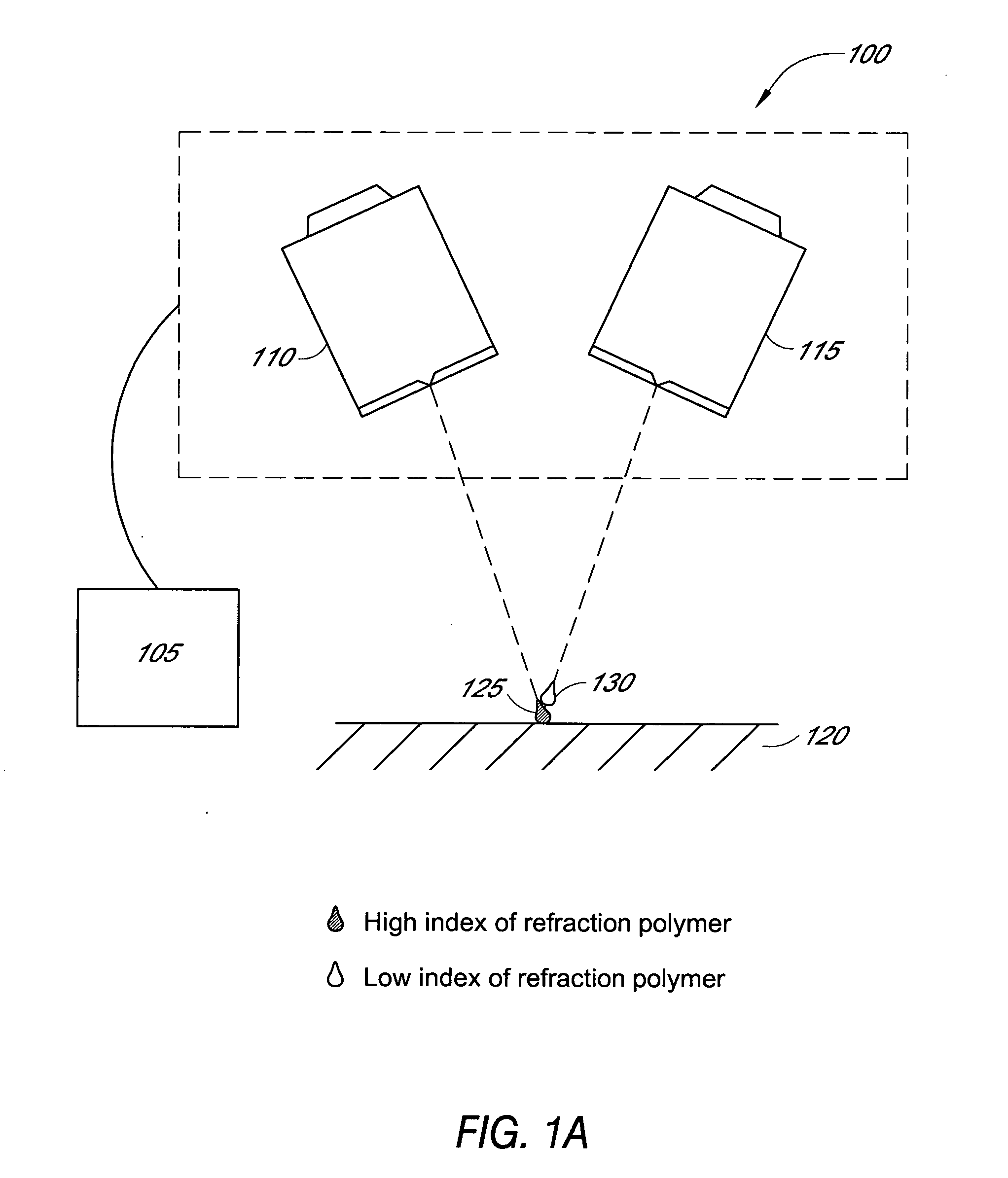
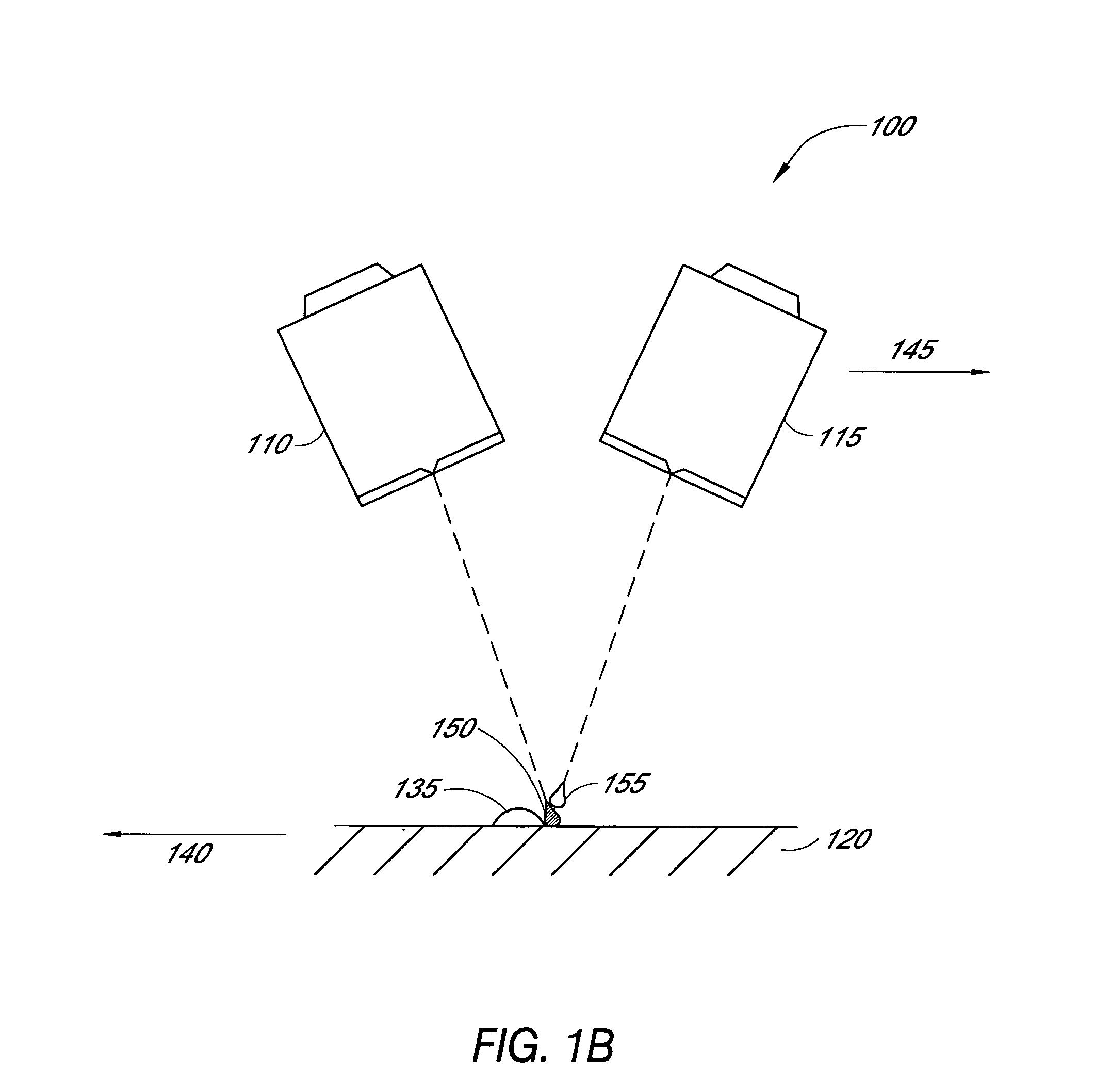
Optical elements are made using micro-jet printing methods to precisely control the type, position and amount of polymer deposited onto a substrate. In preferred embodiments, the proportions of two or more different polymer compositions are varied over the course of the deposition process to deposit adjoining polymer pixels in the form of a film on the substrate surface. The optical properties of each adjoining polymer pixel can be selected to provide a predetermined optical property, including a specific value of index of refraction. Preferably, the film has a radially non-monotonic refractive index profile and / or an angularly non-monotonic refractive index profile.

Description

RELATED APPLICATION INFORMATION [0001] This application is a continuation-in-part of U.S. patent application Ser. No. 10 / 253,956, filed Sep. 24, 2002, which claims priority to U.S. Provisional Patent Application No. 60 / 395,878, filed Jul. 11, 2002, both of which are hereby incorporated by reference in their entireties. Disclosure Document No. 514428, deposited with the U.S. Patent and Trademark Office on Jun. 28, 2002, is also incorporated by reference in its entirety.BACKGROUND OF THE INVENTION [0002] 1. Field of the Invention [0003] This invention relates to optical elements and methods of making them by using micro-jet printing methods to precisely control the type, position and amount of polymer deposited onto a substrate. [0004] 2. Description of the Related Art [0005] Optical elements such as eyeglass lenses are typically made by casting, grinding and / or polishing blanks made from glass or plastics such as polycarbonate and polyethylene glycol diallyl dicarbonate (CR39). Howev...

Claims


Application Information

Patent Timeline
IPC IPC(8): G02B3/10B29D11/00B41J2/01G02B1/04G02B3/00G02C7/02
CPCB29D11/00355G02B1/04G02C2202/22G02C2202/12G02B3/0087B29D11/00432
Inventor LAI, SHUI T.SVERDRUP, LAWRENCE
Owner ESSILOR INT CIE GEN DOPTIQUE
Learn More