Transcoder and imaging apparatus for converting an encoding system of video signal

a technology of encoding system and imaging apparatus, which is applied in the field of transcoding system conversion and imaging apparatus, can solve the problems of time required, and achieve the effect of reducing the time required for transcoding and reducing the transcoding tim

Inactive Publication Date: 2005-03-03
HITACHI LTD
View PDF8 Cites 41 Cited by
  • Summary
  • Abstract
  • Description
  • Claims
  • Application Information

AI Technical Summary

Benefits of technology

[0007] According to the technique described in Japanese Patent Laid-open No. 2002-152755, the transcoding time can be reduced by eliminating the decoding process (i.e., inverse transformation of transform coefficients). However, in such a transcoder as to be configured to include a decoder for decoding an MPEG stream for display as an image signal, combined with an encoder for encoding / compressing the input image signal into an MPEG stream, eliminating the inverse transformation of transform coefficients does not substantially reduce the time required for transcoding if transcoding is made at a rate of one picture per frame period.

Problems solved by technology

However, in such a transcoder as to be configured to include a decoder for decoding an MPEG stream for display as an image signal, combined with an encoder for encoding / compressing the input image signal into an MPEG stream, eliminating the inverse transformation of transform coefficients does not substantially reduce the time required for transcoding if transcoding is made at a rate of one picture per frame period.

Method used


Image

  • Transcoder and imaging apparatus for converting an encoding system of video signal
  • Transcoder and imaging apparatus for converting an encoding system of video signal
  • Transcoder and imaging apparatus for converting an encoding system of video signal

Examples


first embodiment

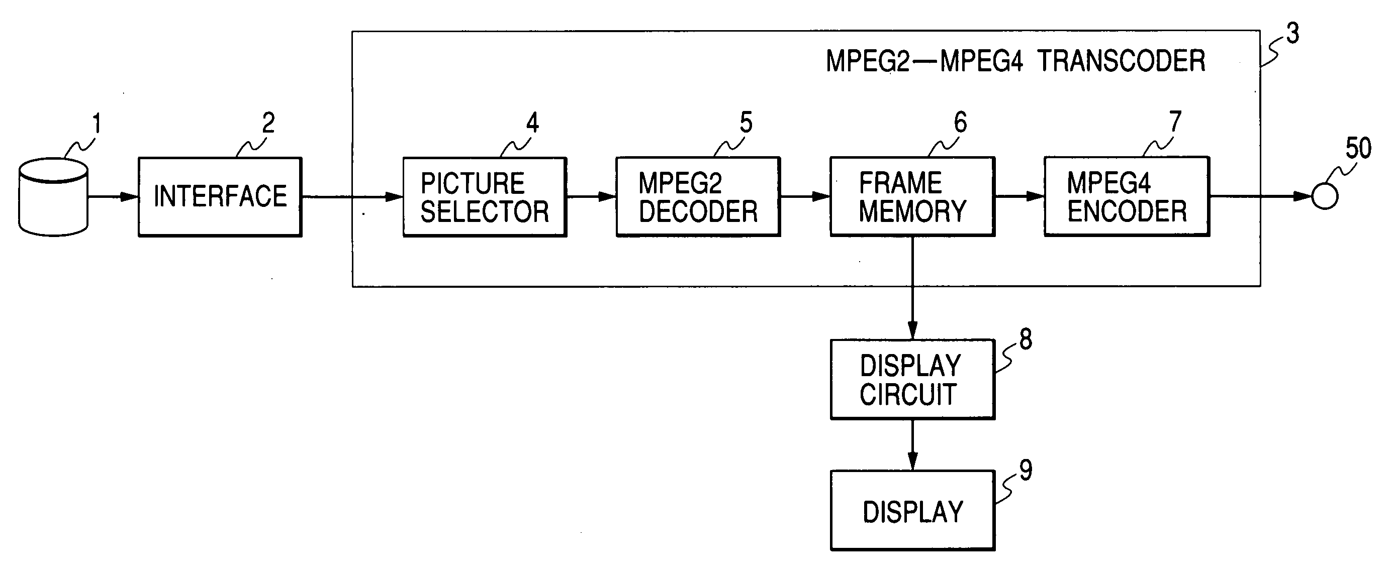
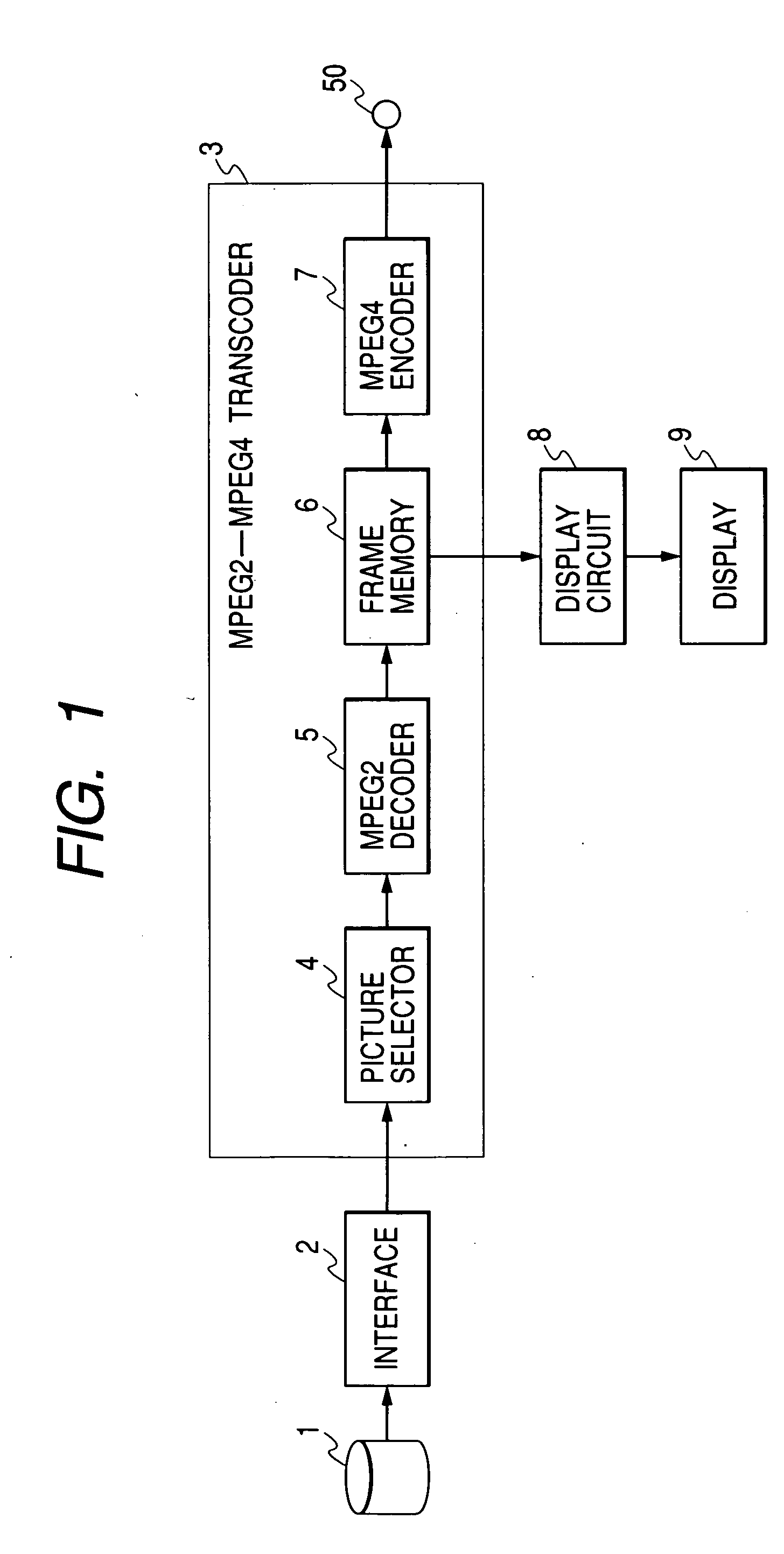
[0019]FIG. 1 shows a block diagram of a transcoder according to the present invention. In FIG. 1, a stream, read out from a recording medium 1, is transcoded by a transcoder 3 and output from an output terminal 50. The transcoder 3 comprises a picture selector 4, an MPEG2 decoder 5, a frame memory 6 and an MPEG4 encoder 7. In addition, the signal accumulated in the frame memory 6 is displayed by a display 9 via a display circuit 8.

[0020] In the transcoder shown in FIG. 1, a MP@ML (main profile at main level) MPEG2 stream (hereafter denoted simply as an MPEG2 / MP@ML stream) is transcoded to a SP (simple profile) MPEG4 stream (hereafter denoted simply as an MPEG4 / SP stream) and output.

[0021] Specifically, it is assumed in the following operational description that a 30 frames / sec MPEG2 / MP@ML stream is transcoded to a 10 frames / sec MPEG4 / SP stream. Firstly, an MPEG2 stream stored on the recording medium 1 such as a DVD is read out by an interface 2 and supplied to the picture selector ...

third embodiment

[0042] That is, in this imaging apparatus described as the third embodiment, it is possible not only to pick up images and record them as a high image quality MPEG2 stream but also to convert it to a low bit rate MPEG4 stream for output to the outside.

[0043] Although the imaging apparatus in FIG. 7 uses the transcoder shown in FIG. 1 as the first embodiment, it is also possible to configure the imaging apparatus by using the transcoder shown in FIG. 5 as the second embodiment. In addition, although the camera unit 10 has the image pickup block 11 therein, it is possible to modify the configuration in such a manner that a video signal receiver is connected in order to input video signals from the outside. It is also possible to modify the configuration so as to connect an MPEG2 stream receiver in order to input MPEG2 streams from the outside.

[0044] Although the first to third embodiments have been described on the assumption that the compressing / encoding format is transcoded from MP...


PUM


Abstract

The time required to transcode an encoded image signal to an image signal encoded by a different encoding method is reduced.
Disclosed herein is a transcoder comprising: a picture selector 4 which extracts specific types of pictures (I- and P- pictures) from a first image signal (MPEG2 stream) and generates a subset of the first image signal; a first decoder 5 which decodes the subset image signal; and a first encoder 7 which encodes the decoded image signal to a second image signal (MPEG4 stream). The picture selector 4 uses the extracted pictures to generate the subset image signal with a reduced effective length.

Description

BACKGROUND OF THE INVENTION [0001] 1. Field of the Invention [0002] The present invention relates to a transcoder for converting the coding format of an image signal and to an imaging apparatus and signal processor using this transcoder. [0003] 2. Description of the Related Art [0004] 3. Prior Art [0005] To record moving image signals on recording media or transmitting them over the Internet, radio and other communication media, techniques for compressing and encoding moving image signals by MPEG and other compressing algorithms have recently been used in various fields. For example, MPEG2-Video (ISO / IEC13818-2) is used for recording to and playing back from DVDs. In addition, MPEG4-Video (ISO / IEC14496-2) is used in radio communication and Internet applications. Including them, a variety of encoding methods have been proposed. With the diversification of encoding methods, however, it has become necessary to transcode data among these formats and improve the transcoding capability. I...

Claims


Application Information

Patent Timeline
Patent Type & Authority Applications(United States)
IPC IPC(8): H03M7/30H04B1/66H04N19/114H04N5/765H04N5/77H04N5/85H04N9/804H04N19/132H04N19/134H04N19/159H04N19/40H04N19/423H04N19/50H04N19/587
CPCH04N5/765H04N5/772H04N5/85H04N9/8042H04N19/159H04N19/577H04N19/61H04N19/132H04N19/162H04N19/587H04N19/40H04N19/172
Inventor YOSHIDA, DAISUKEKOMI, HIRONORIYATABE, YUSUKE
Owner HITACHI LTD
Why Eureka
Try Eureka