Bonding anchor

a technology of anchors and retaining rods, applied in the field of anchors, can solve the problems of laborious setting operation, inability to perfect remove broken down and reduced stones using the prior art centering device, and inability to manufacture at least one centering element in large quantities

Inactive Publication Date: 2005-03-03
HILTI AG
View PDF2 Cites 13 Cited by
  • Summary
  • Abstract
  • Description
  • Claims
  • Application Information

AI Technical Summary

Benefits of technology

[0017] Preferably, for the axial securement of the at least one centering element, a retaining sleeve is provided that can cooperate with the anchor tube, whereby in the region of the second end, an outer thread is formed on the anchor tube in the region of the trailing end of the anchor tube and the retaining sleeve has an inner thread that can be brought into engagement with the outer thread on the anchor tube. The retaining sleeve preferably has a base section, which secures the at least

Problems solved by technology

The drawback of such prior art solution is that in the drilling operation and especially during the dispensing operation, any shifts of the receiving means for the dispensible mass occurring in the anchor tube cannot be taken up by the centering device.
In addition, perfect removal of the broken down and reduced stone is not possible using the prior art centering device, because the passage channels can close up during the drilling operation in the event of a shift in the a

Method used


Image

  • Bonding anchor
  • Bonding anchor
  • Bonding anchor

Examples


Embodiment Construction

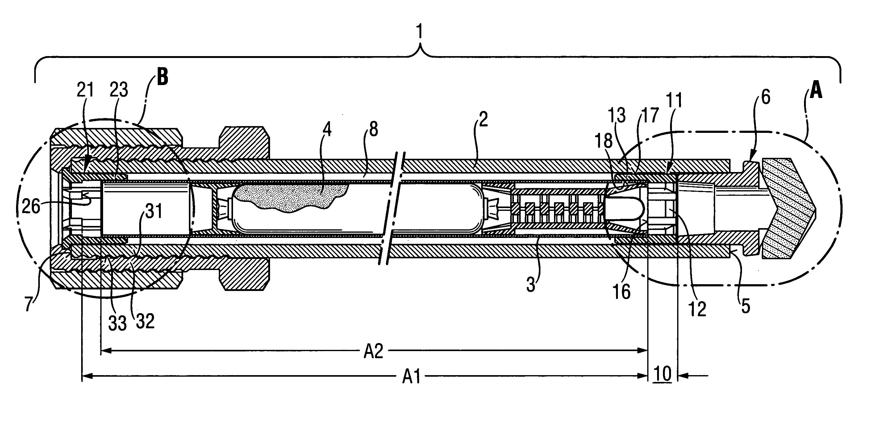
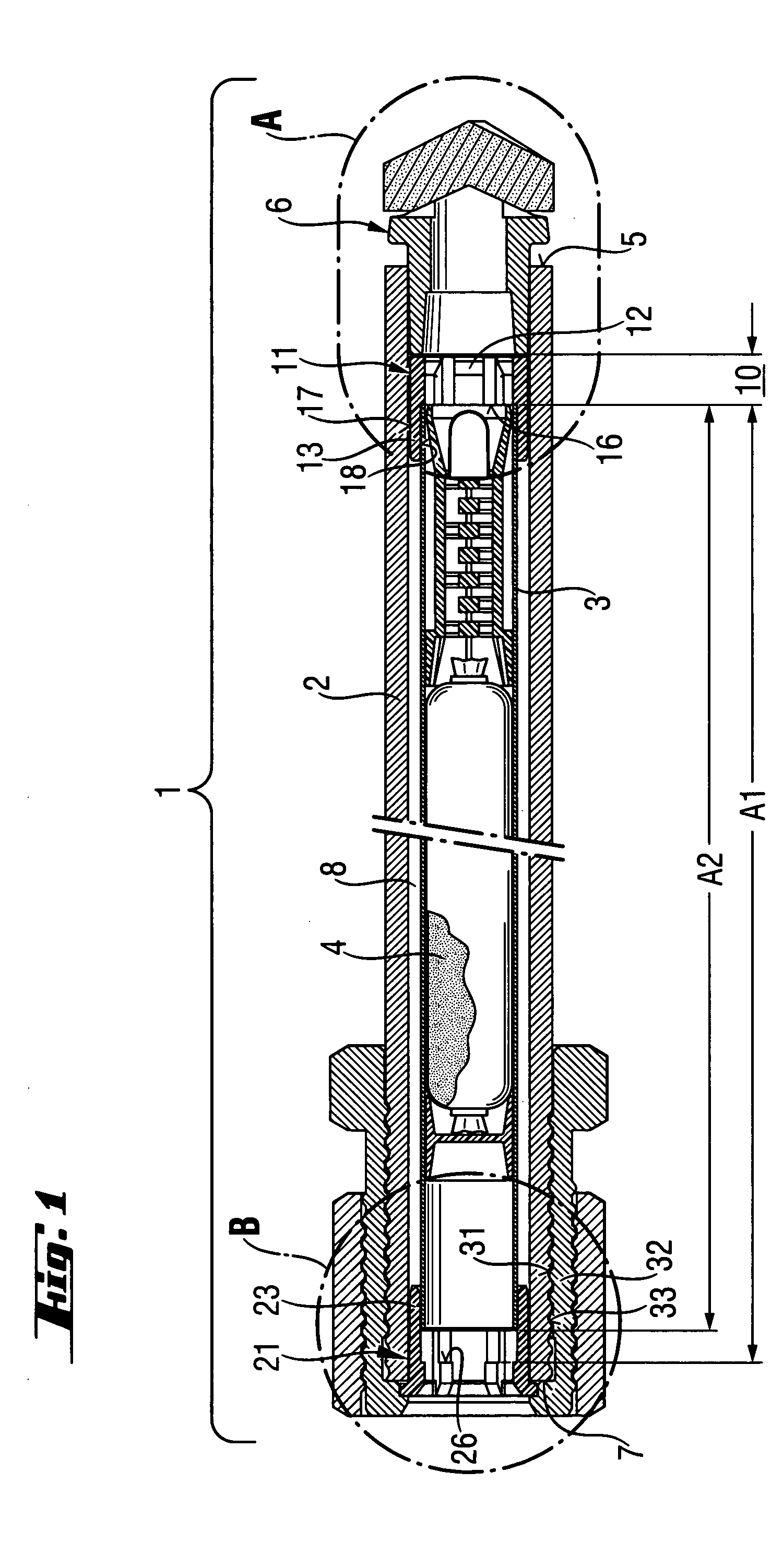
[0027] The anchor 1 is to be based in a region of a receiving material and is formed of an axially extending anchor tube 2 and an axially extending inner tube 3 arranged therein. A dispensable mass 4 packaged in a foil bag is arranged in the inner tube 3. The anchor tube 2 has a first leading end 5 with an incorporated drill head 6 and an opposite second trailing end 7. The inner tube 3 is radially and axially held by means of a centering assembly including a first centering means 11 and a second centering means 21.

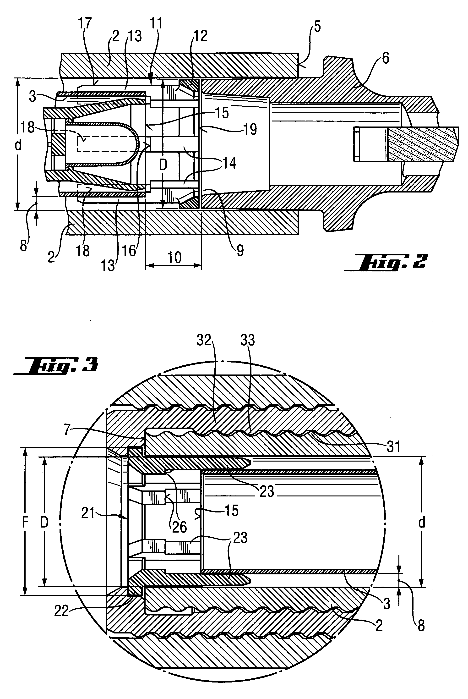
[0028] The first centering means 11 according to FIG. 2 has a ring-shaped base part 12, whose outside diameter D corresponds approximately to the inside diameter d of the anchor tube 2. Six webs 13 extend axially from the base part 12, the webs are uniformly distributed around the periphery of the base part 12. The webs 13 each have a thickened part 14 for the creation of an axial stop surface 16 for the inner tube 3, which projects into the projection of the front and 1...


PUM


Abstract

An anchor (1) comprising an anchor tube (2) and an inner tube (3) arranged in the anchor tube (2) for receiving a dispensable chemical mass (4). The anchor tube (2) has a first end (5) with a drilling head (6) and a second trailing end (7), at which a drilling machine can be coupled for rotary driving of the anchor (1). The anchor (1) further has a centering assembly with a first centering element (11) and a second centering element (21), which hold the inner tube (3) both radially and axially aligned in the anchor tube (2) by means of radial stop surfaces (17, 18) and axial stop surfaces (16, 26).

Description

FIELD OF INVENTION [0001] The invention relates to an anchor to be bonded in a receiving material such as rock and including an anchor tube and a receiving means arranged in the anchor tube, in particular an inner tube, for receiving a dispensible chemical mass. The anchor tube has a first leading end with a drill head and a second, trailing end, at which a drilling device can be coupled for rotary driving of the anchor. The anchor further includes a centering assembly, which has at least one centering element with a radially outer stop surface for co-operating with the inner surface of the anchor tube and a radially inner stop surface for co-operating with the outer surface of the receiving means, the centering element serving in the radial alignment of the receiving means in the anchor tube. BACKGROUND INFORMATION AND PRIOR ART [0002] Self-drilling, chemical bonded anchors and their utilization in mining and tunnel construction have been well-known in the art for a long time. The ...

Claims


Application Information

Patent Timeline
IPC IPC(8): E21D20/02E21D21/00F16B13/14
CPCE21D20/02F16B13/143E21D2021/0053E21D21/0033E21D21/0053E21D21/00
Inventor LUDWIG, WOLFGANGLEIBHARD, ERICH
Owner HILTI AG
Why Eureka
Try Eureka