Modified centrifugal fan wheel

Inactive Publication Date: 2005-03-03
DATECH TECH CO LTD
View PDF6 Cites 7 Cited by
  • Summary
  • Abstract
  • Description
  • Claims
  • Application Information

AI Technical Summary

Benefits of technology

[0013] a set of blades, arranging around an outer part of the hollow hub, having an up ring and a down ring. An inner part of the down ring is connected to the closed part of the hollow hub. Blades are disposed between the up ring and the down ring. Wind holes are disposed equidistantly between each of the blades and eq

Problems solved by technology

Therefore, the airflow entering into the top side of the hollow hub 4 will generate turbulence (as shown in FIG. 10), resulting in difficulty in outputting the air.
Thus, it results in more power consumption and further worsens the performance.
Furthermore, airflow will generate considerable operation noise due to the perforation 43.
Although in t

Method used


Image

  • Modified centrifugal fan wheel
  • Modified centrifugal fan wheel
  • Modified centrifugal fan wheel

Examples


Example

[0025] The following descriptions of the preferred embodiments are provided to understand the features and the structures of the present invention.

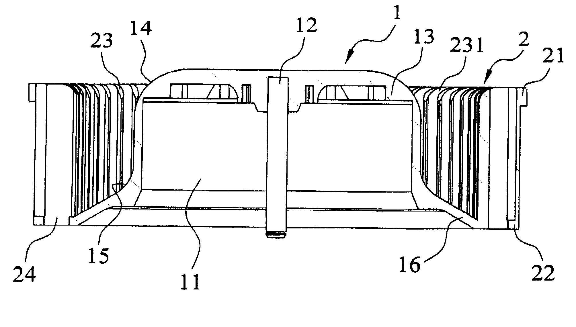
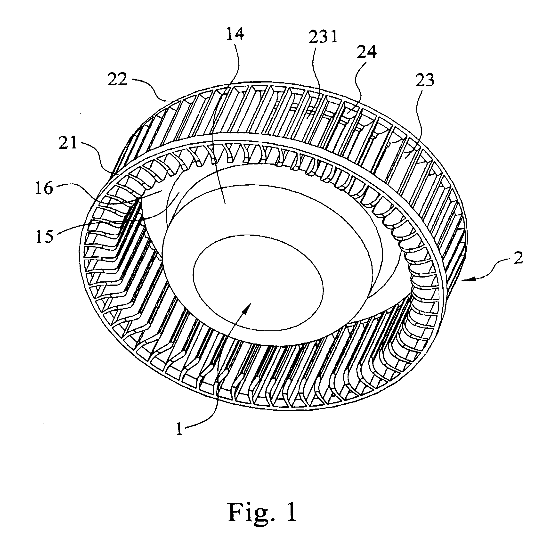
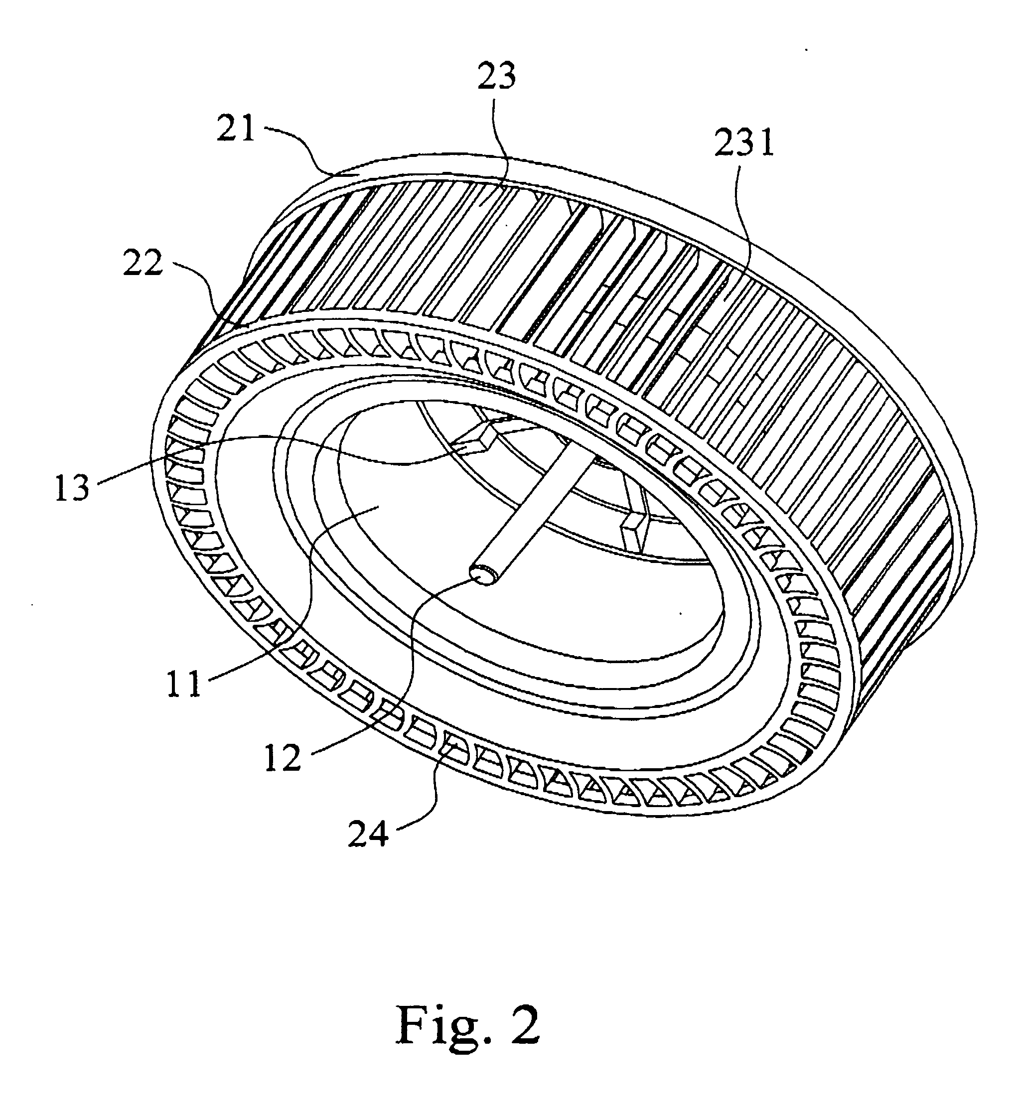
[0026]FIG. 1, FIG. 2, and FIG. 3 are respectively a diagram showing an outward appearance of the present invention, a diagram showing an outward appearance of the present invention viewing from a different angle, and a cross-section diagram of the present invention. As shown in the diagrams, the present invention provides a modified centrifugal fan wheel, comprising a hollow hub 1 having a closed part 16 and a set of blades 2 having perforations 24. By the closed part 16 and the perforation 24, low noise and low current are provided. Meanwhile, power consumption is reduced and working performance of the fan wheel is also improved.

[0027] The hollow hub 1 mention above has a hollow portion 11. A hollow hub axis 12 is disposed at the center of the hollow portion 11 of the hollow hub 1. Ribs 13 are disposed at the hollow portion 11 of the h...


PUM


Abstract

The modified centrifugal fan wheel comprises a hollow hub and a set of blade. A hollow hub axis is disposed at the center of a hollow portion of the hollow hub. Along a top side surface of the hollow hub is a curved guiding inlet part and along a bottom side surface of the hollow hub is a curved surface with a smooth fillet extending to a closed part. A set of blades is arranged around an outer part of the hollow hub, having an up ring and a down ring. An inner part of the down ring is connected to the closed part of the hollow hub. Blades are disposed between the up ring and the down ring. Wind holes are disposed equidistantly between each of the blades and equidistant perforations are arranged on the surface of the down ring, connecting to the wind holes between each of the blades. By the closed part and the perforation of the fan wheel, low noise and low current are provided. Meanwhile, power consumption is reduced and working performance of the fan wheel is also improved.

Description

REFERENCE CITED [0001] 1. U.S. Pat. No: 2003 / 0143070A1 FIELD OF THE INVENTION [0002] The present invention is related to a modified centrifugal fan wheel. More particularly, by a closed part and a perforation, during operation of the fan wheel, noise is reduced and the current value is lowered. Meanwhile, the power consumption for operation of the fan wheel is reduced and working performance is also improved. BACKGROUND OF THE INVENTION [0003] The structure of conventional fan wheel is shown in FIG. 9. The fan wheel has a hollow hub 4. A connecting part 41 is arranged in the bottom of the hollow hub 4, having a side extend to at least one blade 42. At least one perforation 43 is disposed between the hollow hub 4 and the blade 42 on the surface of the connecting part 41. Thus, a fan wheel is formed. [0004] Although the fan wheel mentioned above can be fabricated in a fan case (not shown) in order to guide airflow, however, since both the top side of the hollow hub 4 and joint portion...

Claims


Application Information

Patent Timeline
IPC IPC(8): F04D29/28
CPCF04D29/283
Inventor LI, NIEN-LUNWANG, FU-YIN
Owner DATECH TECH CO LTD
Why Eureka
Try Eureka