Failover method in a redundant computer system with storage devices

a computer system and storage device technology, applied in the field of computer systems, can solve the problems of system inability to efficiently take over the processing of data, the failure of the first detection of failure to the actual takeover of the system, and the inability to recover destroyed data

Inactive Publication Date: 2005-03-03
HITACHI LTD
View PDF8 Cites 58 Cited by
  • Summary
  • Abstract
  • Description
  • Claims
  • Application Information

AI Technical Summary

Benefits of technology

[0030] The present invention thus provides a high availability database system, which, when a failure accompanying data corruption occurs in the active computer system, protects the data from the failure to recover the valid data prior to the data destruction and to achieve a failover using the data.

Problems solved by technology

However, the detection of a fault in the cluster program is programmed so as to prevent the taking over of tasks due to a temporal error or a mistakenly detected failure, such that the tasks are taken over to the stand-by system only when the failure is detected repeatedly a given number of times. As a result, there exists a delay from the first detection of failure to the actual take-over of the system process.
If the failure which has occurred in the active system is destructive due to a bug in an application or due to a runaway condition of the system, then some of the data will be destroyed during this period, so that the destroyed data will not be recoverable.
Therefore, there is a problem that the stand-by system cannot efficiently take over the processing of the data.
In this system, there is a problem that the disk replication is not properly completed in case of a failure of abnormal disk-to-disk communication, not to mention the case of a bug in an application or a runaway condition.
A method in which data to be taken over may be protected by shadowing the data from the primary vol to the secondary vol by using this volume replication function, in order to recover from the non-corrupted status, can be devised, however, there will be problems in such method.
First, if the data replication is enabled, corrupted data may be copied to the destination so that the data in the secondary vol, the subject to be protected, may also be corrupted.
Second, if the data capacity is huge in such a case as a database system, the backup process may take a few hours, resulting in a difficulty of frequent backup operations.
In addition, there also is another problem in that the recovery of the data status at the time of failure from the backup data may involve a lot of time and effort.
The prior methods, as described above, have the following problems: When a system failure occurs in the active / backup computer systems having commonly shared primary and secondary VOLs that are subject to be replicated therebetween (pair configuration / pair split), and when the stand-by system takes over the process in the active system, if a failure that has occurred in the active computer system involves data corruption, the data to be taken over may be subject to the risk of corruption, so that the fail-over will have failed.
If there is a failure involving data corruption, the failover works only after the data has been corrupted.
However, as the amount and capacity of data is continuously increasing, the complete backup interval is set longer, so that the time taken for the recovery of valid data immediately prior to a failure will be enormously long.
As can be seen from the foregoing, the methods employed heretofore have a problem of requiring an enormous time for recovering the same data along with a valid system in case of a failure that involves data corruption, when using a cluster system for the purpose of increased reliability.

Method used


Image

  • Failover method in a redundant computer system with storage devices
  • Failover method in a redundant computer system with storage devices
  • Failover method in a redundant computer system with storage devices

Examples


Embodiment Construction

[0044] It should be appreciated that the drawings and description of the present invention is simplified, for the sake of clarity, to indicate appropriate elements for clear understanding of the invention, and some known elements which are not essential for the practice of the invention are omitted. It is also to be understood that there are many known preferable and / or essential technologies for the implementation of the present invention, however they involve elements that are well known and do not assist in providing an understanding of the invention and therefore are not described in greater detail herein.

[0045] A detailed description of some preferred embodiments embodying the present invention will be given with reference to the accompanying drawings.

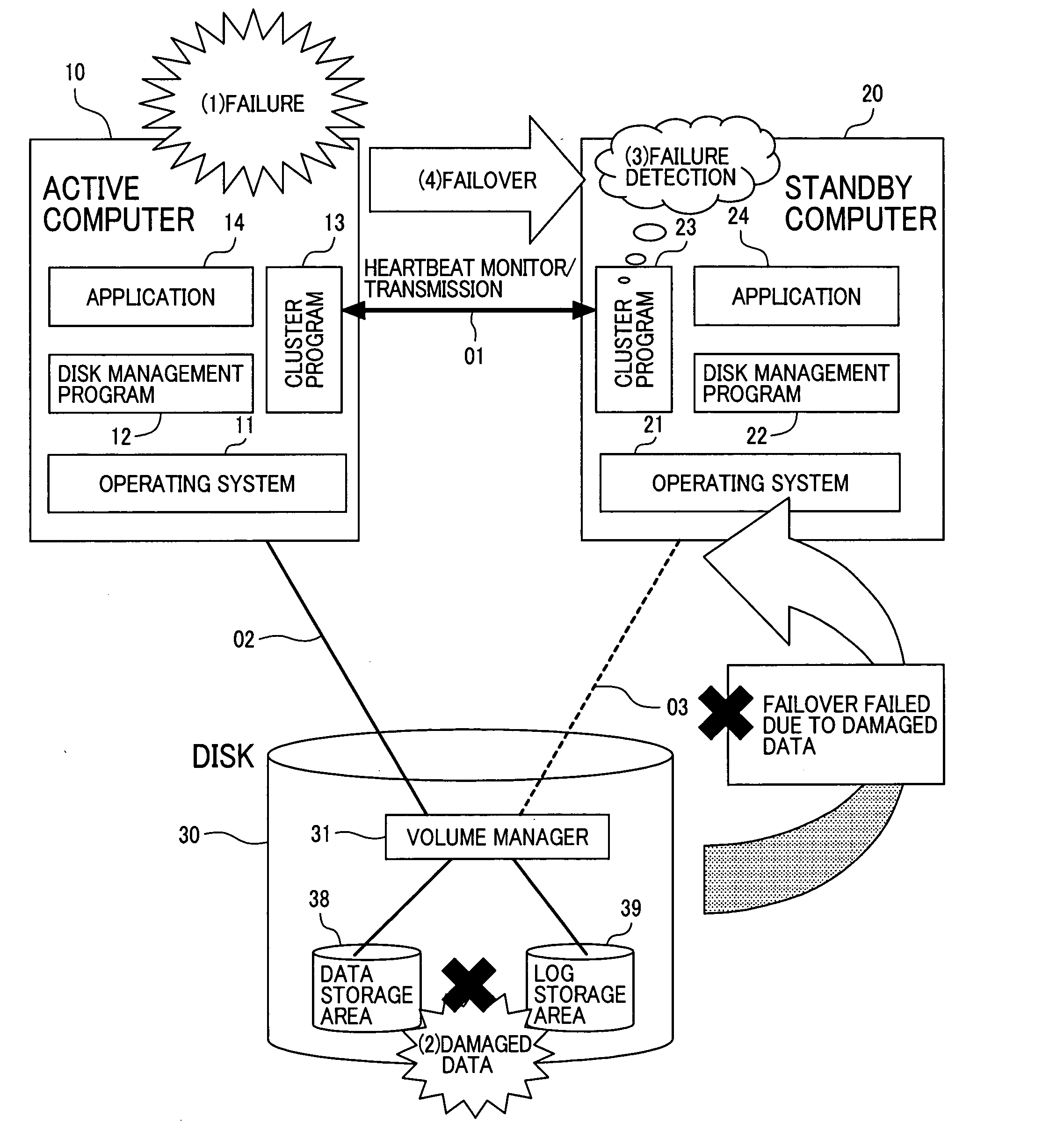
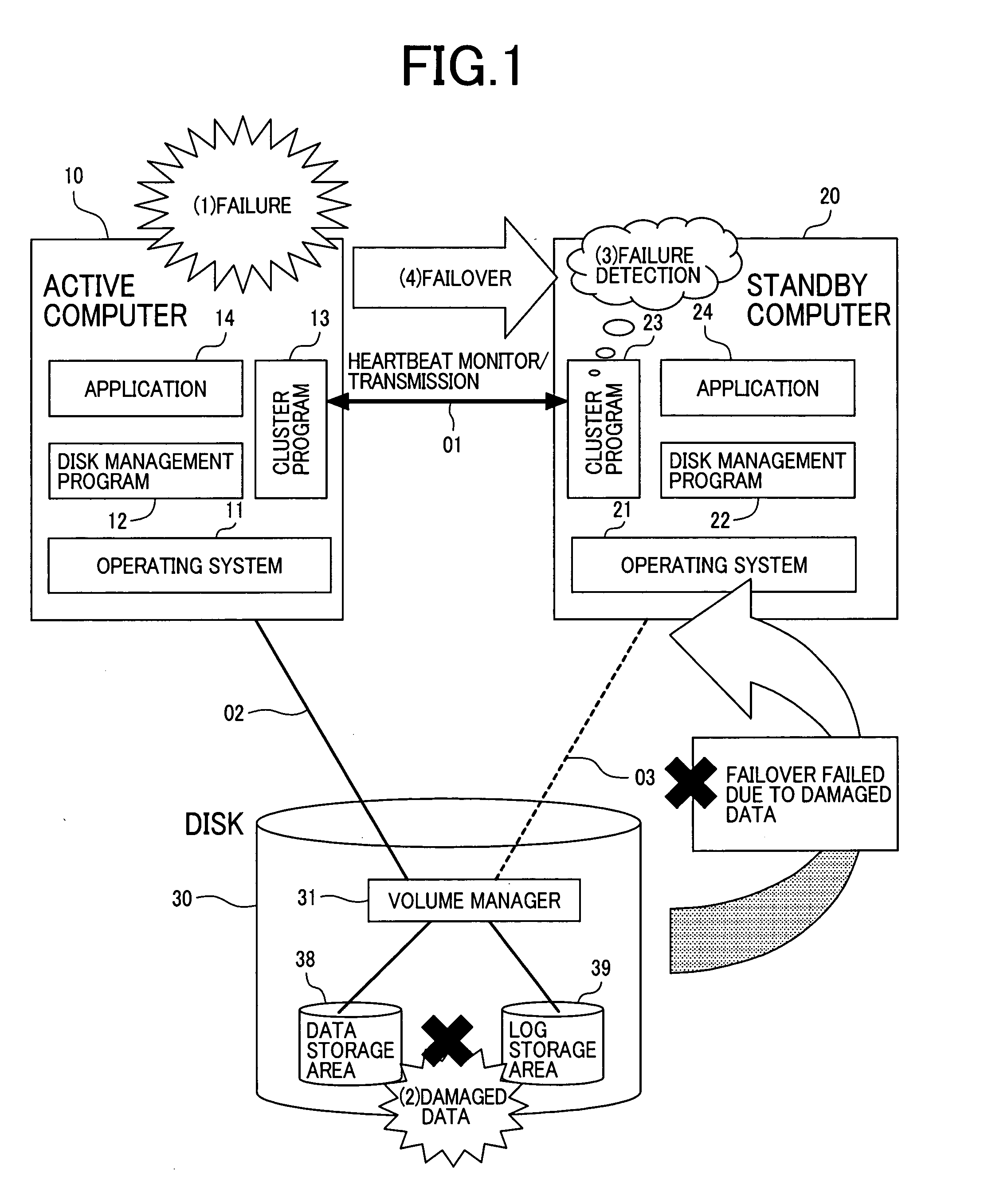
[0046]FIG. 1 is a schematic block diagram which illustrates the problem to be solved by the present invention in a superior system of a known active / stand-by computer system model.

[0047] Although FIG. 1 and the description that...


PUM


Abstract

A high availability database system, subject to a failure causing data corruption in the active server system, may recover valid data prior to the corruption, and use the protected and recovered data to effect a failover. At the time T1 when a stand-by computer system detects the occurrence of a failure, a pair split is done to the data area to protect the data area time T0, just before the occurrence of the failure, and another pair split is done to the log area at the time, where the log area is corrupted or a time T3, where the failover is to take effect without corrupting data, to protect the log area containing data at a given time between time TO and time T3. By using the data and log areas thus protected, the stand-by computer system may take over valid data and log areas of the given time to perform a failover.

Description

CROSS-REFERENCE TO RELATED APPLICATION [0001] This application is related to a U.S. application Ser. No. 10 / 766,802, filed Jan. 30, 2004, entitled “Method, Apparatus and Computer Readable Medium for Managing Multiple System”, the disclosure of which is hereby incorporated by reference.CLAIM OF PRIORITY [0002] The present application claims priority from Japanese application JP2003-300713, filed on Aug. 26, 2003, the content of which is hereby incorporated by reference into this application FIELD OF THE INVENTION [0003] The present invention is related to a computer system with a fault tolerance for building a data base system; and, in particular, the invention is relates to a computer system incorporating a program that prevents the contents of a replicated volume from being destroyed, among volumes available to execute a volume replication procedure, in a case in which the computer program or operating system performing the volume replication procedure between a pair of volumes has...

Claims


Application Information

Patent Timeline
Patent Type & Authority Applications(United States)
IPC IPC(8): G06F11/00G06F11/20G06F12/00
CPCG06F11/2023G06F11/2084G06F11/2069G06F11/2038
Inventor BABA, TSUNEHIKOFUJIWARA, SHINJISUZUKI, YOSHIO
Owner HITACHI LTD
Why Eureka
Try Eureka