Fault injection method and system

a fault injection and fault technology, applied in error detection/correction, instruments, computing, etc., can solve the problems of limiting the use of b-s in many applications, unable to connect input and output points of equipment hardware for injection of fault conditions, and increasing difficulty in direct pin access

Inactive Publication Date: 2005-03-03
LUCENT TECH INC
View PDF8 Cites 34 Cited by
  • Summary
  • Abstract
  • Description
  • Claims
  • Application Information

AI Technical Summary

Benefits of technology

[0016] The present invention includes a system for fault injection of a circuit device, which uses existing IEEE 1149.1 Boundary Scan standard compliant resources without modification, and which can be implemented by existing installed operating systems. The system has, a fault selection circuit adapted with fault selection data identifying selected circuit outputs of the circuit device, a fault value circuit adapted with fault values for injection on corresponding selected circuit outputs, and the fault selection circuit controlling the selected circuit outputs in place of system logic control during the injection of respective fault values.

Problems solved by technology

However, the equipment hardware would lack input and output connection points for injection of fault conditions, because of crowded micro-processors, FPGAs and ASICs on typical circuit boards, and due to imbedding of interconnection points in interior layers of the typical circuit boards.
Thus, as IC pin counts increase, pin spacing decreases, and direct pin accessibility becomes increasingly difficult, boundary scan (B-S) is playing an increasing role in design verification, manufacturing, and the testing of new products.
The requirement that all pins are controlled by the same logic (that is, for the same chip, some pins cannot be controlled by system logic while others are controlled by B-S registers), however, limits B-S usage for many applications, for example, those applications requiring fault injection.
It is very difficult and sometimes impossible to perform these system verification tasks via simulations at the board or system level.
Usually only a handful pins are selected to be modified for fault injection due to a number of problems, such as restriction of physically accessible pins of highly dense package devices on a board, possible damage to the devices, lengthy labor intensive process to set up the physical fault injection, and so on.
Hence, not only the resulting fault coverage is low but also the test process is very expensive.
And the application can not be implemented in previously installed operating systems, because they have previously existing IEEE 1149.1 boundary scan standard compliant architecture, which do not have modified BS cells, and which can not be tested with modified TAP controllers.
However, neither the implementation of the fault injection instruction nor the enhancement of the B-S cell to support fault injection have been given.
Although no modification of the TAP and B-S register is required at all to use this method, it is not sufficient in most of system verification.
However, in the first design, the faulty value to be injected must be identical on all selected pins.
However, there are two main drawbacks of this design: (i) the fault injection selection data, which were previously shifted into the update FF of the B-S register, are corrupted when entering the update state of the TAP controller while the fault injection values are shifted in; (ii) the logic values of the fault injection pins are rippling when the fault injection values are shifting into the capture FF of the B-S register.
There are also some compliance issues with the IEEE 1149.1 Boundary Scan standard.
The previously proposed systems and methods do not fulfill a present need for a fault injection system and method that uses existing IEEE 1149.1 Boundary Scan standard compliant resources without modification, and which can be implemented by existing installed operating systems.
Further, the previously proposed systems and methods do not fulfill a present need for a fault injection system and method that is operative in system mode.

Method used


Image

  • Fault injection method and system
  • Fault injection method and system
  • Fault injection method and system

Examples


Embodiment Construction

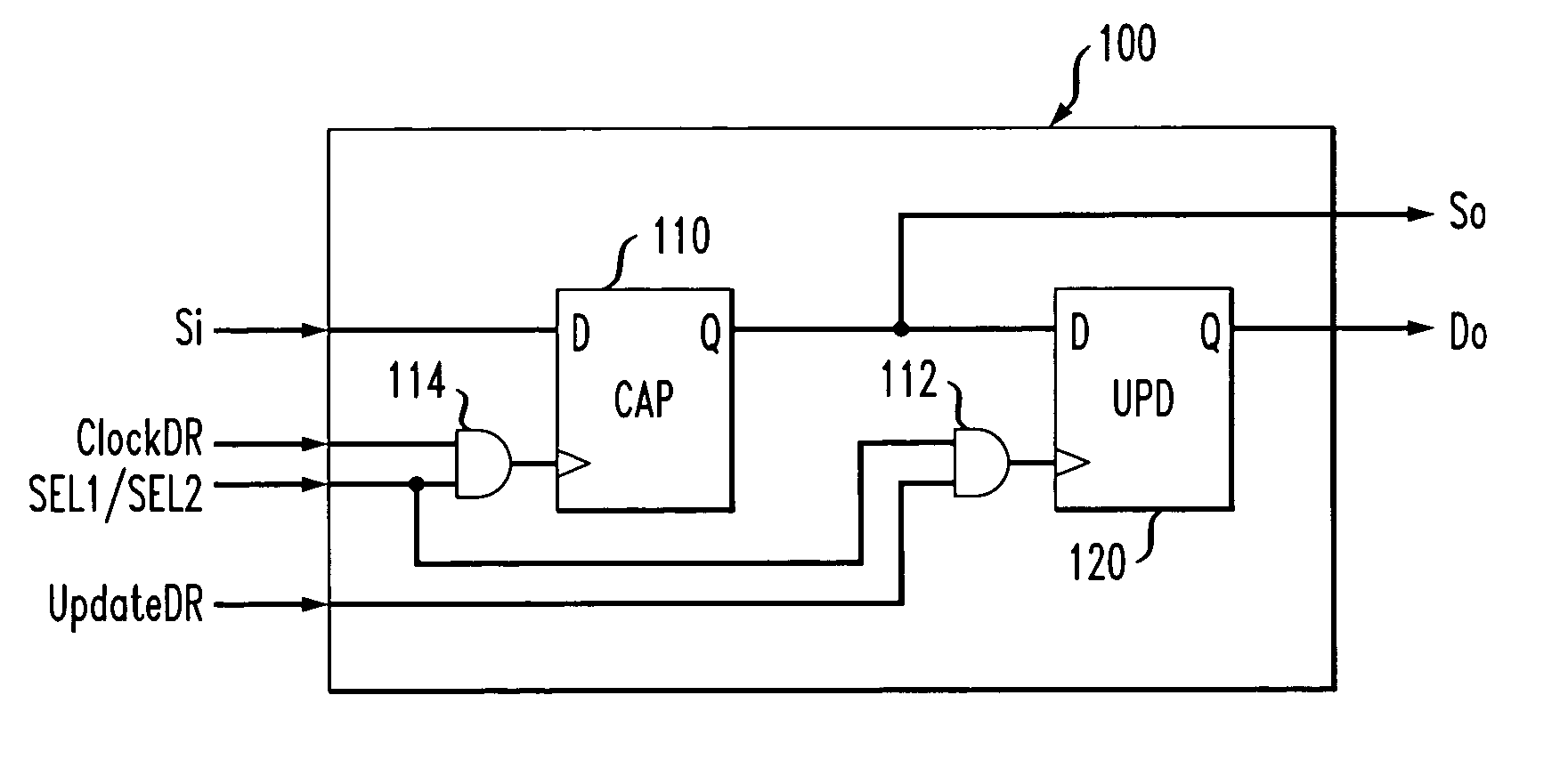
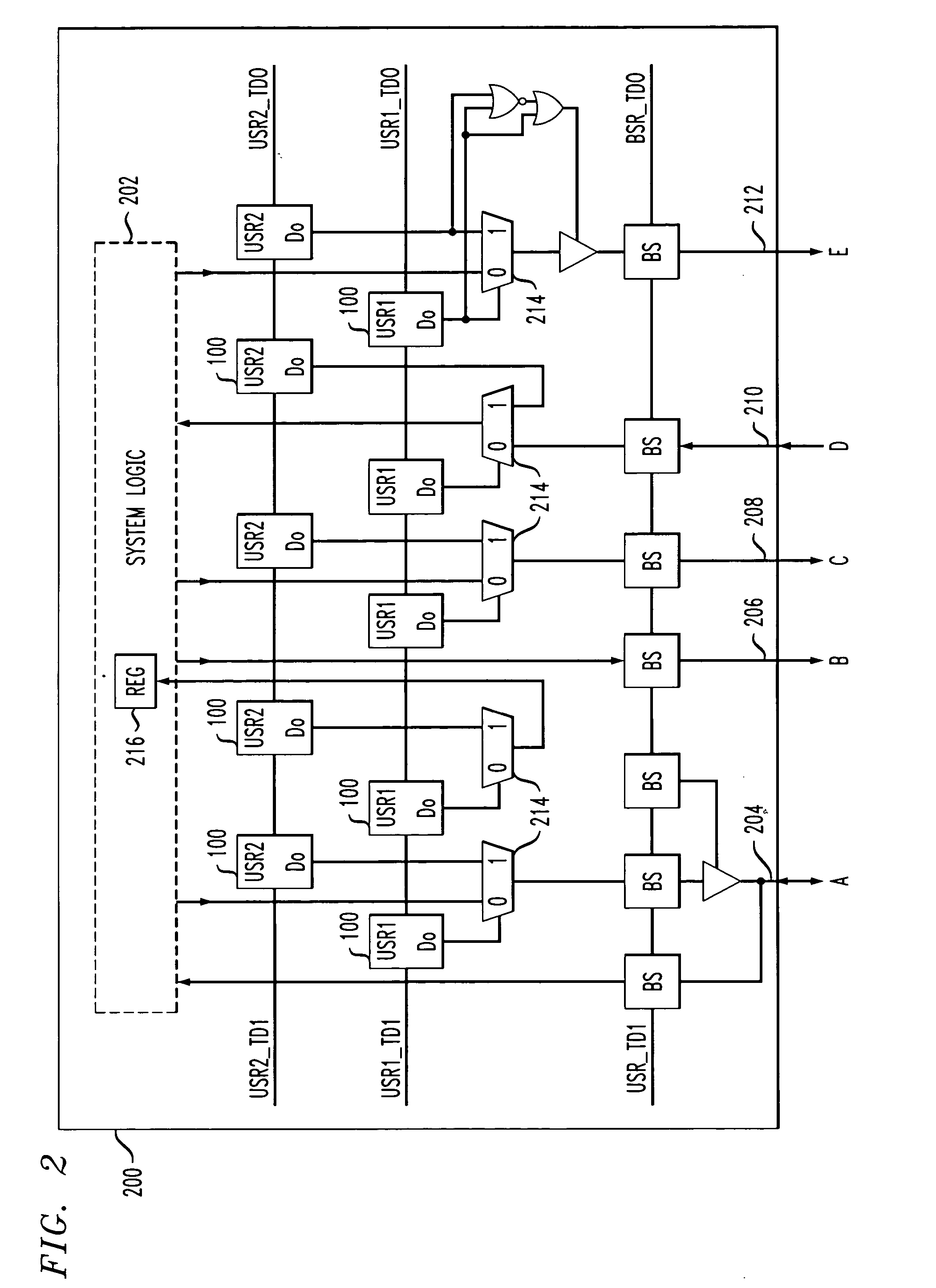
[0024] The present invention comprises a novel fault injection (e.g., fault insertion) system and method to facilitate the development of high quality system testing. The method and system relies on existing boundary scan resources, without requiring modification, to inject a fault value at a selected output, which includes, but is not limited to, a pin and a fault injection functional internal register of a Field Programmable Gate Array (FPGA). When a pin is referred to herein, the pin means an output, input or bidirectional input-output where fault injection is desired. Further, when an FPGA is referred to herein, the FPGA means a programmable semiconductor device, including, but not limited to, a programmable gate array, a programmable read only memory, and an integrated circuit device having programmable or burnable fuses.

[0025] The invention injects fault values while the FPGA is in system mode, rather than in boundary scan mode. Thus, the invention uses existing and unmodifie...


PUM


Abstract

A method and system are disclosed for fault injection using Boundary Scan resources compliant with 1149.1, while operating in system mode. The system has two register circuits, one, for storing and updating fault selection data and another, for storing and updating fault injection values.

Description

FIELD OF THE INVENTION [0001] This present invention relates to automatic testing for faults in integrated circuits, and more particularly, to a fault injection method and system. BACKGROUND OF THE INVENTION [0002] Equipment hardware that must perform system operations without interruption is continuously monitored by system diagnostic software. The diagnostic software monitors the equipment hardware for detection of fault conditions, and switches the system operations to run on redundant circuitry that would avoid the fault condition. The system diagnostic software itself needs to be tested. Fault injection is a procedure involving the injection of fault conditions directly on equipment hardware to test the systems diagnostic software for response to the injected fault conditions. However, the equipment hardware would lack input and output connection points for injection of fault conditions, because of crowded micro-processors, FPGAs and ASICs on typical circuit boards, and due to ...

Claims


Application Information

Patent Timeline
Patent Type & Authority Applications(United States)
IPC IPC(8): G06F11/00
CPCG01R31/318541
Inventor CHAKRABORTY, TAPAN J.CHIANG, CHEN-HUAN
Owner LUCENT TECH INC
Why Eureka
Try Eureka