Hydraulic power generation system based on water pumping by weight of water

a technology of water pumping and water weight, applied in the direction of positive displacement liquid engine, electric generator control, machine/engine, etc., can solve the problems of economic inefficiency, only available solar energy, and insufficient space efficiency, and achieve the effect of simple and easy operation

Inactive Publication Date: 2005-03-10
CHIANG KUD CHU
View PDF4 Cites 41 Cited by
  • Summary
  • Abstract
  • Description
  • Claims
  • Application Information

AI Technical Summary

Benefits of technology

[0012] (4) Further, the operation of the system of the present invention can be

Problems solved by technology

However, the solar energy is only available in areas having regular and intense sun light and can only be collected in day times. In addition, solar panels may occupy a great space and is thus not space efficient.
The wind power generation is also available in limited areas around the world, for it needs constant and strong winds to

Method used


Image

  • Hydraulic power generation system based on water pumping by weight of water
  • Hydraulic power generation system based on water pumping by weight of water
  • Hydraulic power generation system based on water pumping by weight of water

Examples


Embodiment Construction

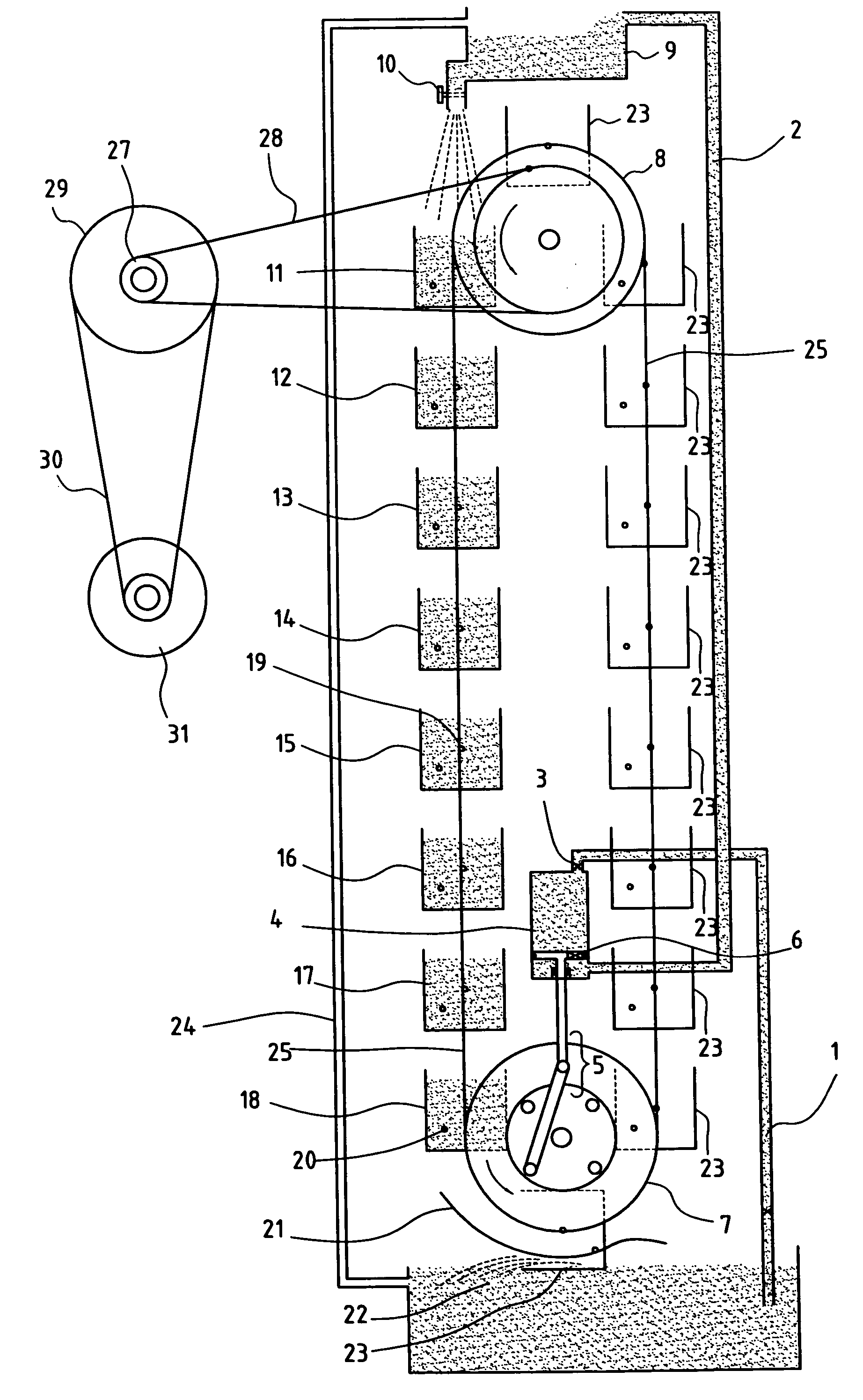
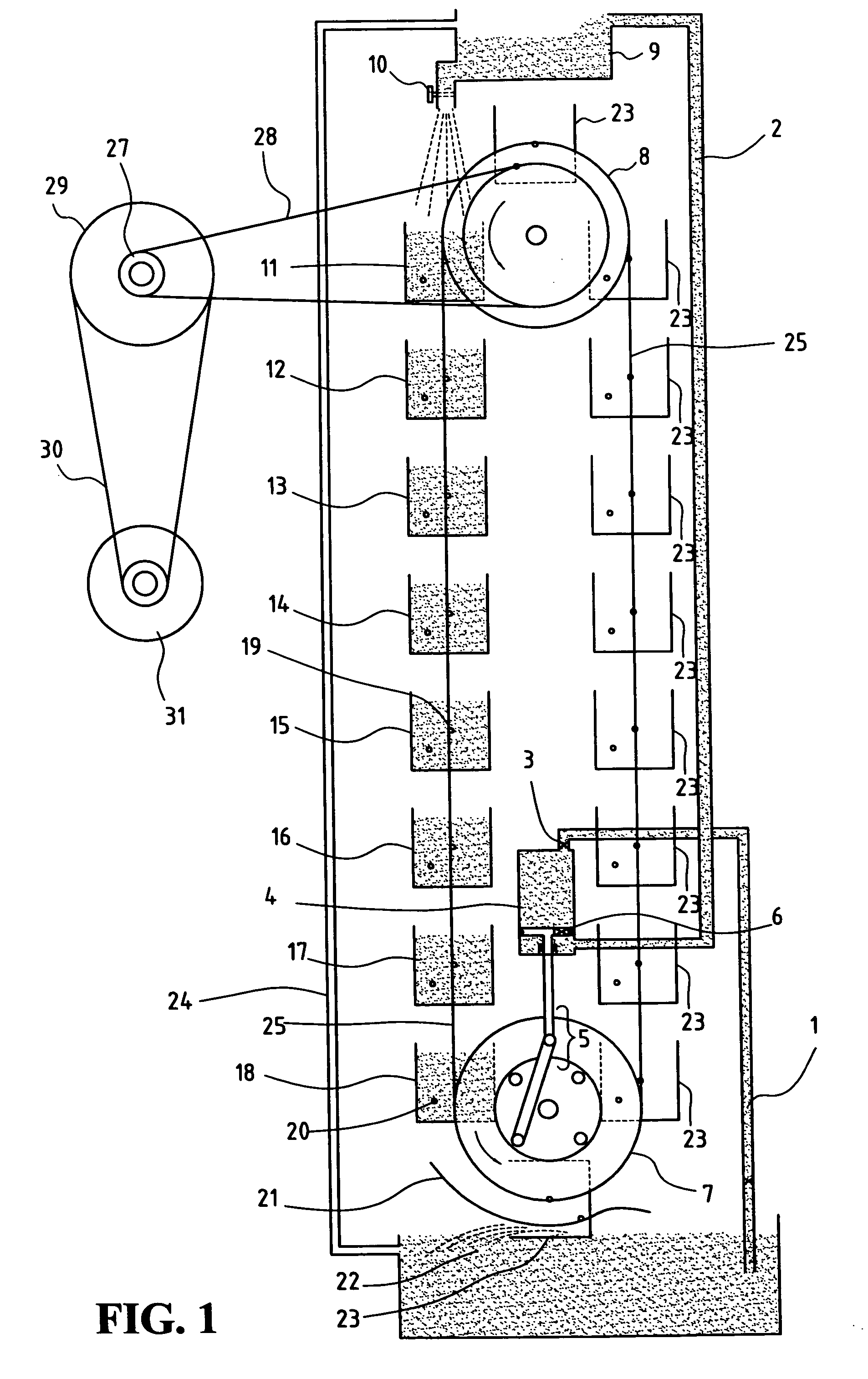
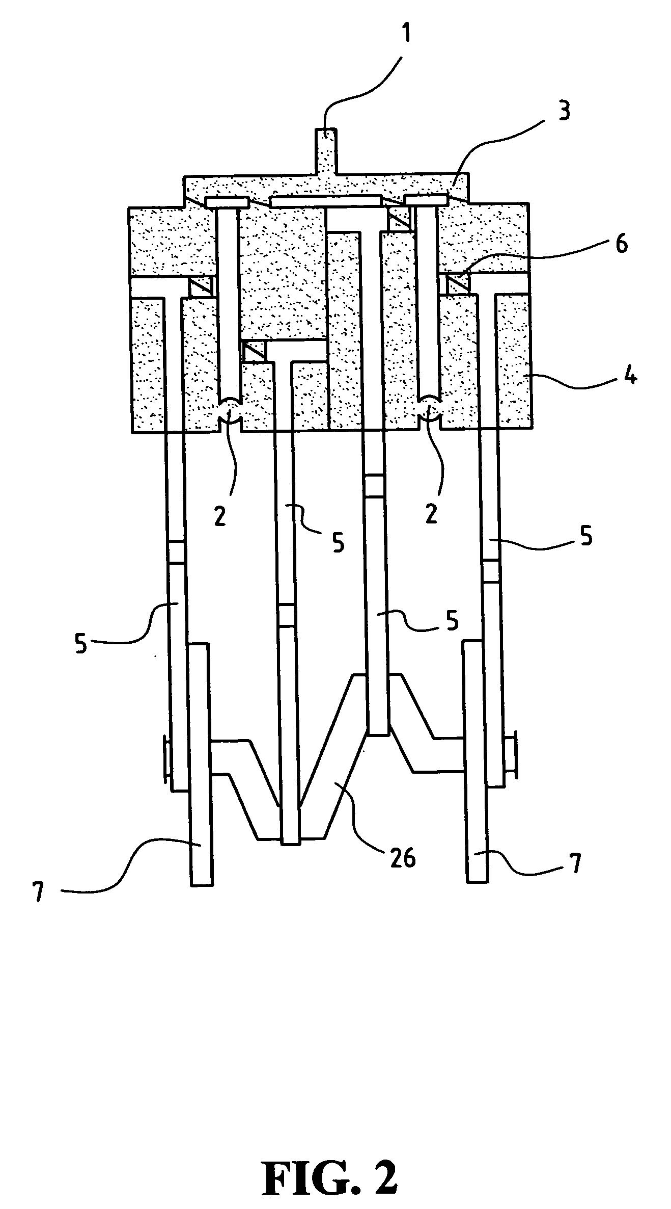
[0017] With reference to FIGS. 1 and 2, which shows an embodiment of a hydraulic power generation system constructed in accordance with the present invention, the hydraulic power generation system comprises a water intake pipe 1, a water discharge pipe 2, a one-way valve 3, water pumping cylinders 4, a set of link and crank arm 5, a water pumping piston one-way valve 6, a driving wheel 7, an auxiliary wheel 8, a water dispensing tank 9, a flow control switch 10, a plurality of driving buckets 11-18, a plurality of bucket shafts 19, a plurality of guiding rods 20, a guiding track 21, a water reservoir 22, a plurality of empty buckets 23, an overflow drainage pipe 24, a transmission chain 25, a crankshaft 26, toothed wheels 27, a chain 28, an accelerating pulley 29, a belt 30 and a generator 31.

[0018] To couple the present invention with the water pumping cylinders, the transmission chain 25 is arranged between the driving wheel 7 and the auxiliary wheel 8, both being symmetric betwe...


PUM


Abstract

A hydraulic power generation system employs a plurality of buckets carried by an endless chain to receive water falling from height and drive the chain, which in turn drives a water pumping device to raise water to the height for automatic and continuous generation of power.

Description

BACKGROUND OF THE INVENTION [0001] 1. Field of the Invention [0002] The present invention relates to the field of hydraulic power generation, and in particular to a hydraulic power generation that employs a plurality of buckets carried by an endless chain to receive water falling from height and drive the chain, which in turn drives a water pumping device to raise water to the height for automatic and continuous generation of power [0003] 2. Description of Related Art [0004] As the natural power source is dying out, people are seeking alternative power to substitute fossil energy that plays the most important role of energy supply for the modern society. Solar energy, hydraulic energy, and even wind energy are the most promising solution for the time being. However, the solar energy is only available in areas having regular and intense sun light and can only be collected in day times. In addition, solar panels may occupy a great space and is thus not space efficient. The wind power ...

Claims


Application Information

Patent Timeline
IPC IPC(8): F03B13/00F03B9/00F03B17/00F03B17/04F04B19/00H02P9/04
CPCY02E10/20F03B17/005
Inventor CHIANG, KUD-CHU
Owner CHIANG KUD CHU
Why Eureka
Try Eureka