Industrial robot system

a robot system and robot technology, applied in the field of industrial robot systems, can solve the problems of limiting the system as to the extent to which a tpu is allowed to operate, and the control unit will break the data link to the tpu, so as to avoid a sudden shutdown of the robot system and increase the accuracy of the control of the industrial robot system

Inactive Publication Date: 2005-03-10
ABB (SCHWEIZ) AG
View PDF14 Cites 32 Cited by
  • Summary
  • Abstract
  • Description
  • Claims
  • Application Information

AI Technical Summary

Benefits of technology

[0044] The security arrangements are programmed to in some way accept the TPU getting closer to the control unit within said chosen time limit. Consequently, if the TPU comes close enough to the control unit, or alternatively enters a work area A in due time, the operation stop will be reset and the robot reactivated. According to the invention, the display of the TPU gives information to the operator concerning the reason for a broken data link. In one embodiment, the display also informs the operator in which direction he and the TPU shall move for entering the area A. Then, the operator has the possibility to move fast into the area A and thereby avoiding a sudden shutdown of the robot system. The solution according to the invention increases the accuracy of the control of the industrial robot system.

Problems solved by technology

There is a limit built into the system as to how far from the control unit a TPU is allowed to operate.
These distances, directions and defined areas are invisible but an important security limitation since an operator has difficulties in knowing where to be positioned.
Thus, if an operator, bringing a wireless TPU connected to the robot, is walking too far away from the control unit, the control unit will break the data link to the TPU.

Method used


Image

  • Industrial robot system
  • Industrial robot system
  • Industrial robot system

Examples


Embodiment Construction

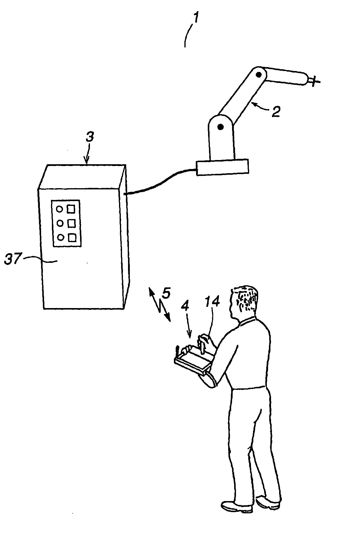
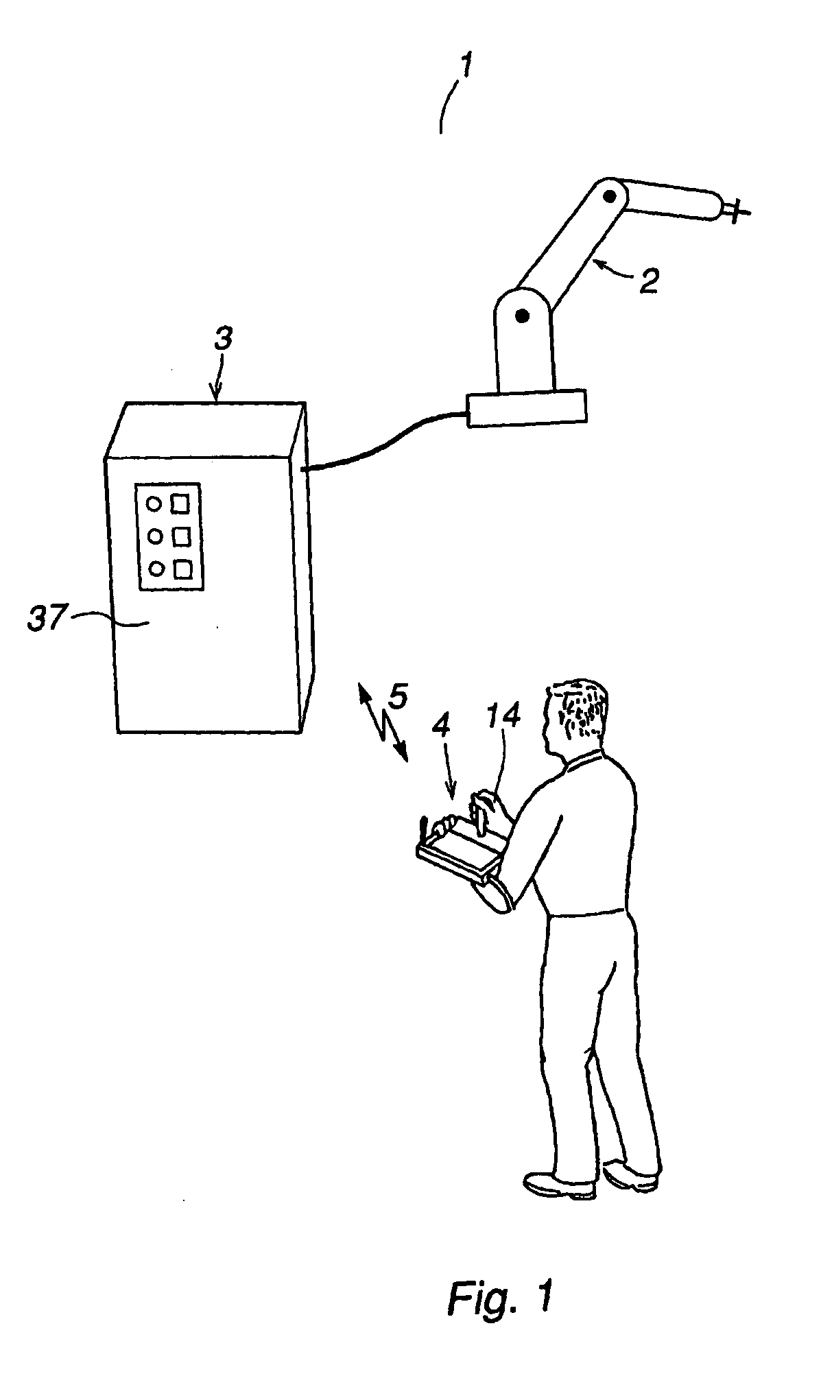
[0055]FIG. 1 is a communication system comprising an industrial robot 1, including a manipulator 2 and a control unit 3 for controlling the manipulator. A TPU 4, for teaching and manually operating the manipulator, is communicating with the control unit 3 via a wireless data link 5. The TPU includes an antenna 6 for wireless communication with the control unit 3.

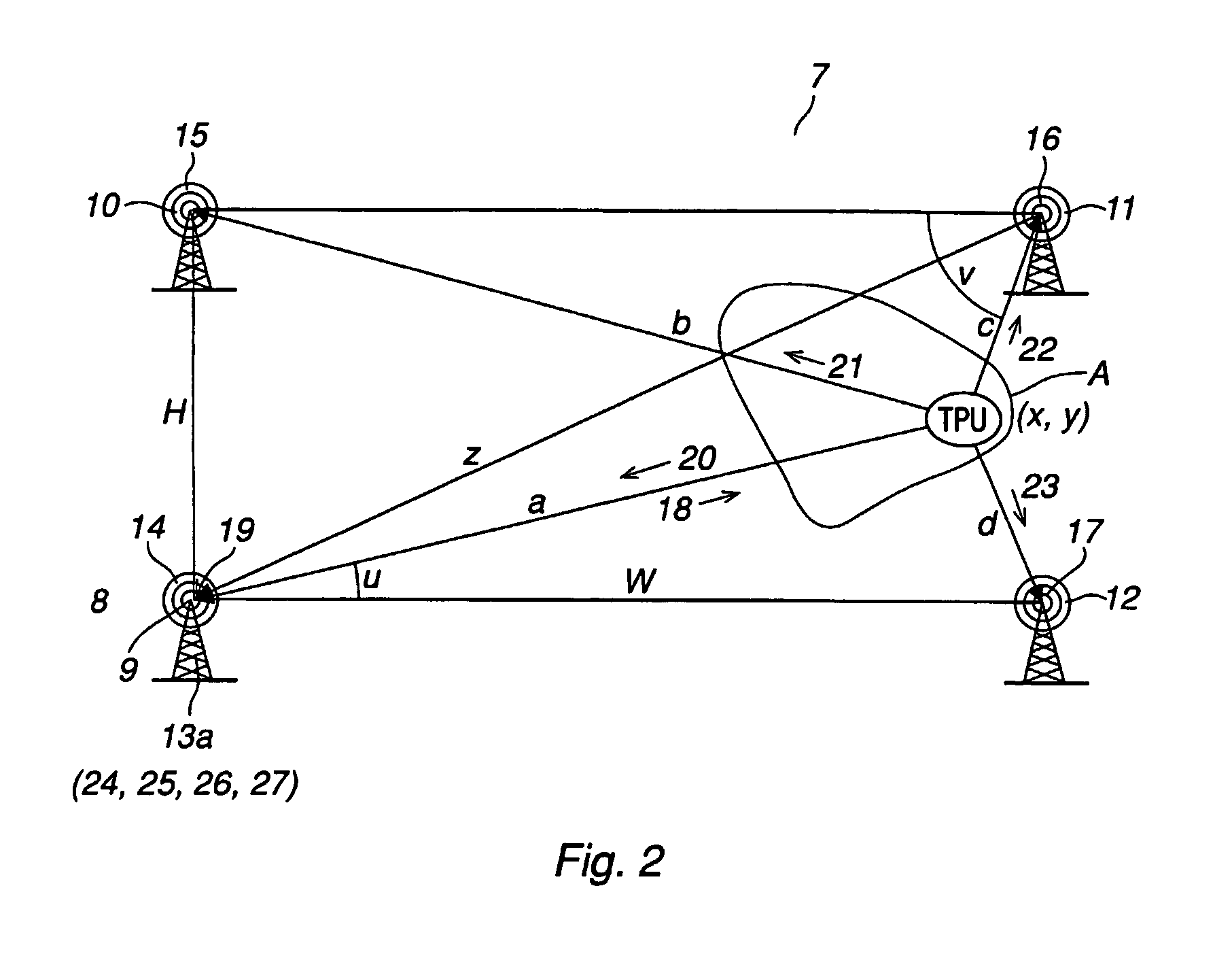
[0056] In FIG. 2, the position determining means 7 comprises a reference station 8 including a first radio tower 9 and means for measuring time 13a. Another three radio towers 10, 11 and 12 are arranged at a distance from each other and from the reference station 8. Each radio tower 9, 10, 11 and 12, respectively, comprises a signal receiving means 14, 15, 16 and 17, respectively. A signal 18 is sent to the TPU 4 from a transmitter 19 arranged in the reference station 8. The time measuring means 13a is measuring a time interval starting when the signal 18 is sent to the TPU 4 and ending when the respective receiving means 1...


PUM


Abstract

The present invention relates to an industrial robot comprising a manipulator (2), a control unit (3) for controlling the manipulator, a portable operating unit (4) for teaching an manually operating the robot, which operating unit is adapted for wireless communication with the control unit and comprising a operator control means (9). The invention increases the safety by ensuring that the operator is within the specified operating area.

Description

TECHNICAL FIELD [0001] The present invention relates to an industrial robot system, including a manipulator and a control unit having means for automatically operating the manipulator. A portable operator control device is connected to the control unit having means for teaching and manually operating the manipulator. The invention also relates to a method for controlling an industrial robot system. Especially the invention relates to a communication control. Particularly the invention relates to a wireless teach pendant unit. [0002] An operator control device is a portable operator control device denoted a teach pendant unit, TPU, in the following. A TPU normally comprises operator control means and a visual display unit. The operator control means usually is a joystick, a ball, a set of buttons or any combination of these. BACKGROUND OF THE INVENTION [0003] An industrial robot is programmed to carry out work or a work cycle along an operating path. In order to program or teach the ...

Claims


Application Information

Patent Timeline
Patent Type & Authority Applications(United States)
IPC IPC(8): B25J13/02B25J13/06B25J19/06F16P3/14G01S5/14
CPCB25J13/02B25J13/065B25J19/06F16P3/147G01S5/14F16P3/141F16P3/144F16P3/14B25J13/006
Inventor CARLSON, ERIKENDRESEN, JANKJESBU, SNORRE
Owner ABB (SCHWEIZ) AG
Why Eureka
Try Eureka