
Temperature sensor circuit for microdisplays

a temperature sensor and microdisplay technology, applied in the field of liquid crystal on silicon (lcos) displays, can solve the problems of insufficient accuracy of the microdisplay system, inconvenient limited effectiveness of a conventional temperature sensor that uses a diode as a variable resistor, etc., to achieve convenient and flexible determination of operation modes, improve resistance noise, and improve the effect of temperature measurement accuracy

Inactive Publication Date: 2005-03-10
JASPER DISPLAY
View PDF6 Cites 36 Cited by
  • Summary
  • Abstract
  • Description
  • Claims
  • Application Information

AI Technical Summary

Benefits of technology

It is therefore an object of the present invention to provide new and improved circuit configurations by applying the proportional to absolute temperature (PTAT) type of temperature measurement to improve the accuracy of temperature measurements. Instead of measuring resistance variations across a distance of diode, a technique of temperature determination using frequency measurements is performed in this invention through a voltage control oscillator. The measurement circuits disclosed in this invention are more compatible with the use of a flexible PCA connection to the microdisplay to a board. The basic circuit of this invention achieved an improved resistance noise and provides additional operation modes with added benefits of more conveniently and flexibly determining an operation mode to overcome the measurement noises. Furthermore, measurement of frequency as carried out by this invention improves the measurement accuracy and reduces the likelihood of false temperature readings.

Problems solved by technology

Since microdislay systems, especially the liquid crystal on silicon (LCOS) Microdisplay frequently operate in the hot interior of a projection device, the microdisplay technology is still challenged by the need to accurately measure the temperature and to control the temperature within appropriate range such that the quality of display would not be impaired by uncontrolled high temperatures.
Specifically, the effectiveness of a conventional temperature sensor that uses a diode as a variable resistor is limited by a system architecture that requires the system resistance from a distance.
Such measurements usually do not provide sufficient accuracy for the microdisplay systems, particularly as all components within such the Microdisplay devices have performance characteristics that are temperature dependent.
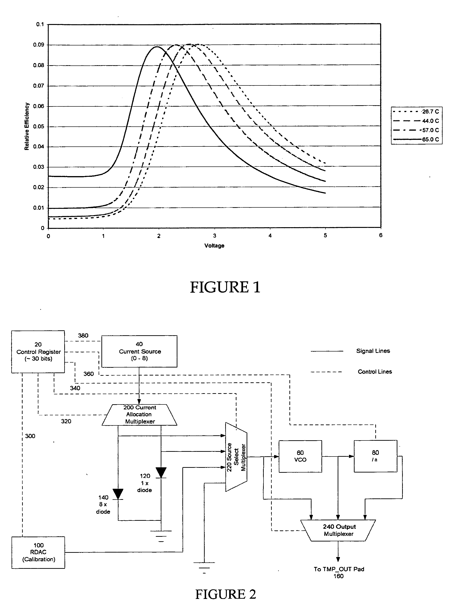
One particular aspect of this temperature driven effect is that the dark state rises as temperature deviates from the design temperature and therefore the contrast of such a system suffers.
Second, the intensity of the achievable dark state rises as temperature rises.
Third, the location of the peak of the voltage curves shifts to lower voltages as the temperature rises.
Fourth, the height of the peak of the voltage curve drops slightly as temperature rises.
Additionally, several unobvious designs can be implemented that can exploit by using an accurately measured temperature to achieve optimal performance from such devices under circumstances of widely varying temperature.
However, such devices would still require the use of a robust temperature sensor because there are device performance parameters such as switching speed still change significantly as the temperature varies even when operated in such electro-optic modes.

Method used


Image

  • Temperature sensor circuit for microdisplays
  • Temperature sensor circuit for microdisplays
  • Temperature sensor circuit for microdisplays

Examples


Embodiment Construction

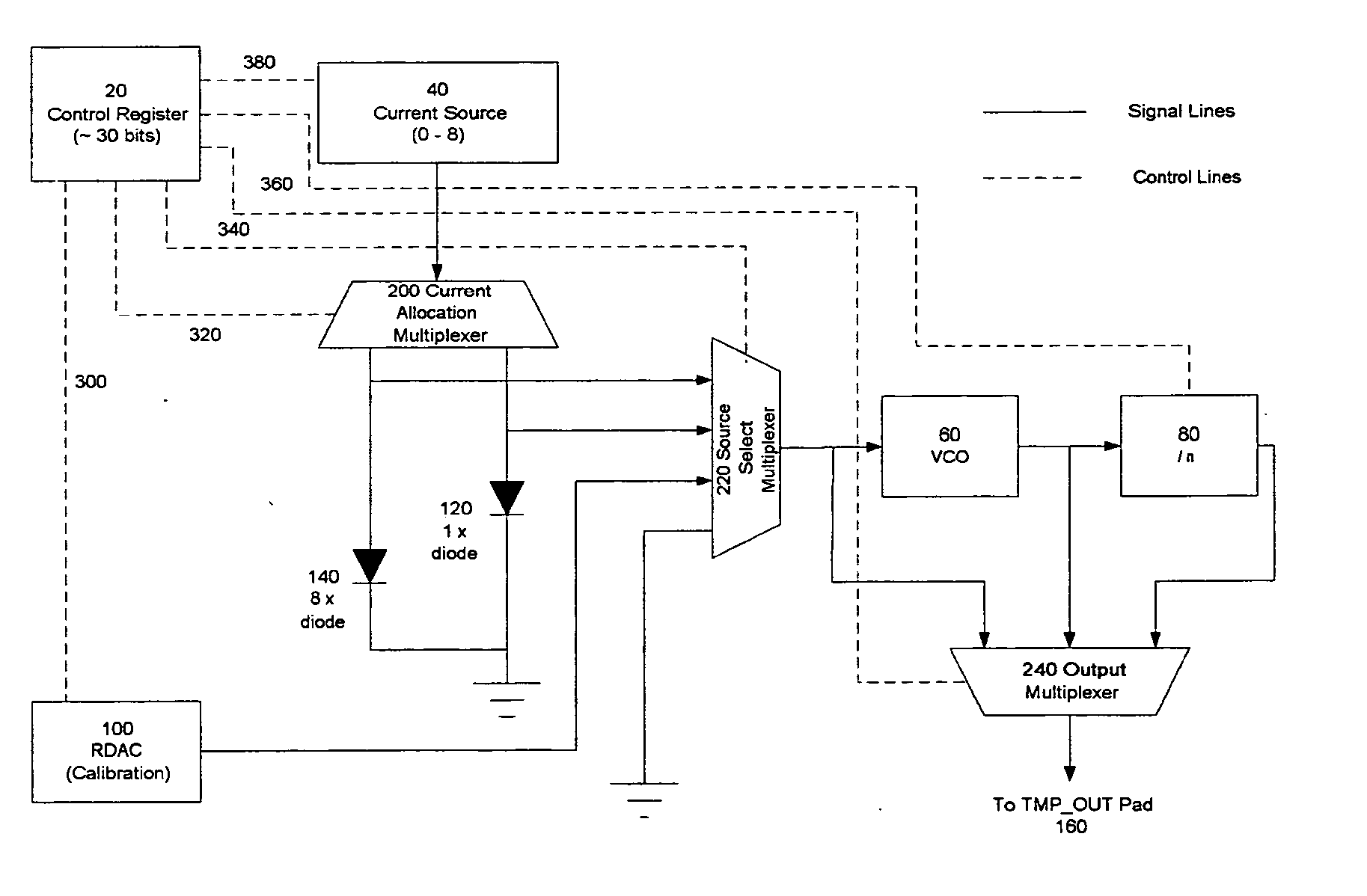
Referring to FIG. 2 for a functional diagram for showing the circuit configuration of a temperature sensor of this invention. The major components in the temperature circuit include two diodes 120 and 140 of eight-times area difference, e.g., show as 1× for diode 120 and 8× for diode 140. These two diodes thus have eight times difference in resistance when conducting the same amount of current. An adjustable current source 40 that is programmable and digitally controllable to have one to eight times of current are inputted to either one of the diodes 120 or 140 via a current allocation multiplexer 200. The output current from either of these diodes is inputted via a source select multiplexer 220 to a voltage controller oscillator 60 to generate a frequency corresponding to the input current and the output from the VCO 60 is inputted to an n-divider 80. An output for connecting to a TEMP_OUT pad 160 is selected between the raw output from the source selecting multiplex 220, the VCO ...


PUM

PropertyMeasurementUnit
thickaaaaaaaaaa
clearing temperatureaaaaaaaaaa
temperatureaaaaaaaaaa

Abstract

This invention discloses a proportional to absolute temperature (PTAT) type of temperature measurement to improve the accuracy of temperature measurements. Instead of measuring resistance variations across a distance of diode, a technique of temperature determination using frequency measurements is performed in this invention through a voltage control oscillator. The measurement circuits are more compatible with the use of a flexible PCA connection to the microdisplay to a board. The basic circuit of this invention achieved an improved resistance noise and provides additional operation modes with added benefits of more conveniently and flexibly determining an operation mode to overcome the measurement noises. Furthermore, measurement of frequency as carried out by this invention improves the measurement accuracy and reduces the likelihood of false temperature readings.

Description

BACKGROUND OF THE INVENTION 1. Field of the Invention The present invention pertains to liquid crystal on silicon (LCOS) displays, and more particularly to improved temperature sensor design and configuration for liquid crystal on silicon displays with more accurate and direct temperature measurements to achieve better image display. 2. Description of the Prior Art Since microdislay systems, especially the liquid crystal on silicon (LCOS) Microdisplay frequently operate in the hot interior of a projection device, the microdisplay technology is still challenged by the need to accurately measure the temperature and to control the temperature within appropriate range such that the quality of display would not be impaired by uncontrolled high temperatures. Specifically, the effectiveness of a conventional temperature sensor that uses a diode as a variable resistor is limited by a system architecture that requires the system resistance from a distance. Such measurements usually do no...

Claims


Application Information

Patent Timeline
Patent Type & Authority Applications(United States)
IPC IPC(8): G01K7/01G01K13/00G09G5/00
CPCG01K7/015G09G2320/041G01K13/00
Inventor HUDSON, EDWIN LYLE
Owner JASPER DISPLAY
Learn More