Inkjet recording system and inkjet recording method

Inactive Publication Date: 2005-03-10
PANASONIC CORP
View PDF4 Cites 16 Cited by
  • Summary
  • Abstract
  • Description
  • Claims
  • Application Information

AI Technical Summary

Benefits of technology

[0013] The present invention was devised in consideration of the aforementioned conventional problems, and an object of the invention is, in the case where the same image or substanti

Problems solved by technology

The screen printing or the offset printing, however, requires considerable time and cost for creating a printing block and adjusting colors.
Therefore, the fabrication of the DVD-ROM cannot help stopping for a long period of time.
The lifetime of the inkjet recording head depends upon the numbers of times of discharging an ink (hereinafter referred to as the discharging frequencies) of nozzles, and hence, when the discharging frequency exceeds a given value, the recording head cannot exhibit desired performance.
Therefore, in recording the same image on a large scale, a large difference can be easily caused in the discharging frequency among the nozzles.
Thus, there is large dispersion in the discharging frequency

Method used


Image

  • Inkjet recording system and inkjet recording method
  • Inkjet recording system and inkjet recording method
  • Inkjet recording system and inkjet recording method

Examples


embodiment 1

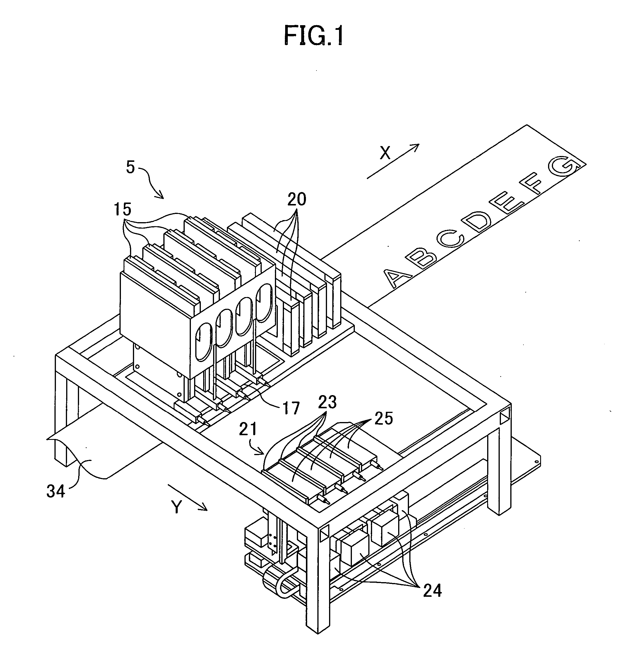
[0037] As shown in FIG. 1, an inkjet recording system according to Embodiment 1 includes a recording device 5 having four inkjet line heads 31 (shown in FIG. 2), so as to form a color image by combining inks of four colors of yellow (Y), cyan (C), magenta (M) and black (Bk). It is noted that an image herein includes one or more of a letter, a line, a symbol, a picture, a photo and the like.

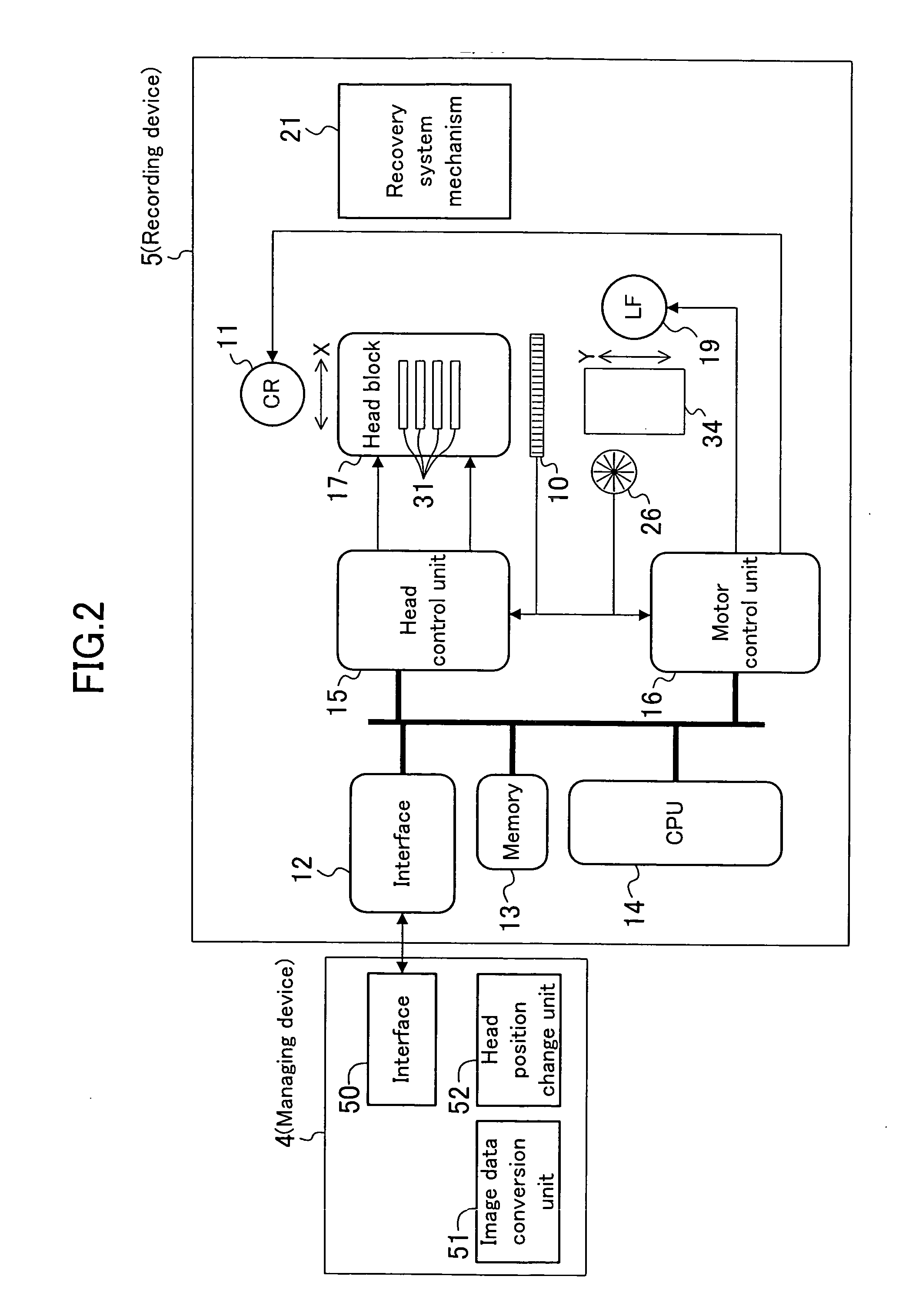
[0038] The recording device 5 includes a head control unit 15 for controlling each line head 31, a head block 17 for positioning and fixing all the line heads 31, an ink tank 20 and a recovery system mechanism 21.

[0039] The recovery system mechanism 21 recovers the performance of each line head 31 and makes each line head 31 exhibit predetermined performance by performing capping for preventing head nozzle faces from drying and a recovery operation for the heads (such as an operation for forcedly discharging an ink or a purging operation). The recovery system mechanism 21 includes caps 25 for co...

embodiment 2

[0068] In Embodiment 2, in changing the combination of used nozzles of the line head 31, image data is converted so as not only to shift an image along the Y direction but also to rotate the image.

[0069] As shown in FIG. 12, an image data conversion unit 51 of this embodiment converts image data so that an image to be recorded can be rotated by 180 degrees (as shown as a position P12 in FIG. 12) as well as shifted along the Y direction (as shown as a position P13 in FIG. 12). The image can be appropriately rotated, and the image may be rotated every time it is shifted along the Y direction (namely, every time the set position of the line head 31 is changed) or rotated regardless of the shift of the image along the Y direction.

[0070] Referring to FIG. 13, the recording operation of this embodiment will be described.

[0071] Prior to the recording operation, in step S11, a total printing number Pt is first set. Next, in step S12, a printing condition switching number Ps is set. The s...


PUM


Abstract

A recording system includes a line head having a plurality of nozzles arranged in a Y direction, a LF motor for feeding a role sheet in an X direction, and a CR motor for shifting a set position of the line head sequentially. When the set position of the line head is shifted by a given distance in the Y direction, the recording system converts image data in such a manner that an image is shifted in an opposite direction by a distance equal to the given distance so that the same image is recorded in different positions of the nozzles.

Description

CROSS REFERENCE TO RELATED APPLICATIONS [0001] This Non-provisional application claims priority under 35 U.S.C. §119(a) on patent application Ser. No. 2003-316481 filed in Japan on Sep. 9, 2003, the entire contents of which are hereby incorporated by reference. BACKGROUND OF THE INVENTION [0002] The present invention relates to an inkjet recording system equipped with an inkjet recording head, and an inkjet recording method. [0003] In order to issue a large number of vouchers in a short period of time, border lines and letters included as the contents of the vouchers are continuously printed on recording paper. In mass production of, for example, read-only CD-ROM disks and DVD-ROM disks, images such as letters and graphics have conventionally been repeatedly and continuously printed on the faces of these disks. [0004] Conventionally, the aforementioned kind of printing has been performed by using a screen printer or an offset printer dedicated to this purpose (see, for example, Japa...

Claims


Application Information

Patent Timeline
IPC IPC(8): B41J2/165B41J2/175B41J3/407
CPCB41J3/4071B41J25/001
Inventor ESAKI, TAKAHIROMIYAZONO, YUTAKAMATSUO, HIDETOSHIHATTORI, HIROSHINAKAGAWA, SEIJI
Owner PANASONIC CORP
Why Eureka
Try Eureka