Integrated start-up circuit with reduced power consumption

a start-up circuit and integrated technology, applied in the field of power supplies, can solve the problems of high power consumption, major power loss in the start-up circuit of known power supplies, and high power consumption, and achieve the effect of reducing the cost of the power supply and reducing the power consumption

Inactive Publication Date: 2005-03-10
SYST GEN
View PDF8 Cites 55 Cited by
  • Summary
  • Abstract
  • Description
  • Claims
  • Application Information

AI Technical Summary

Benefits of technology

[0014] The present invention provides a control-circuit for a switching mode power supply. The control-circuit integrates a start-up circuit, a latch circuit and a line-voltage detector to reduce power consumption.

Problems solved by technology

The main drawback of these circuits is high power consumption.
The drawback of these start-up circuits is also high power consumption because they require primary-side protection circuits.
The start-up circuits of known power supplies are a major source of power loss.
Furthermore, because traditional power supplies typically have high power consumption under light-load and zero-load conditions, it is increasingly difficult to manufacture electrical appliances that are compliant with environmental regulations.
Unfortunately, the input capacitor 40 usually has a large capacitance that may tak

Method used


Image

  • Integrated start-up circuit with reduced power consumption
  • Integrated start-up circuit with reduced power consumption
  • Integrated start-up circuit with reduced power consumption

Examples


Embodiment Construction

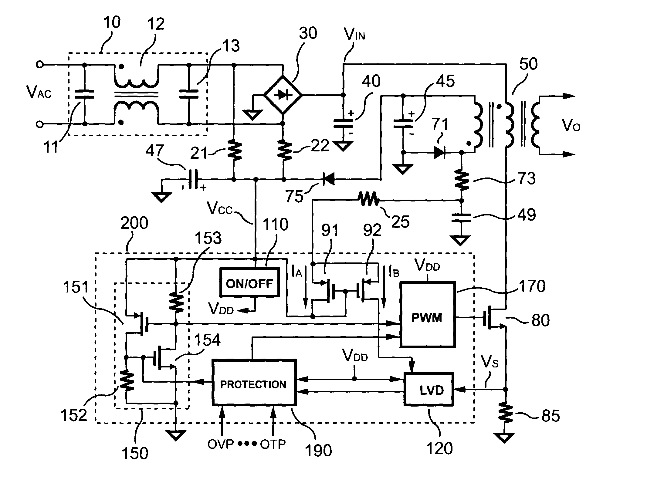
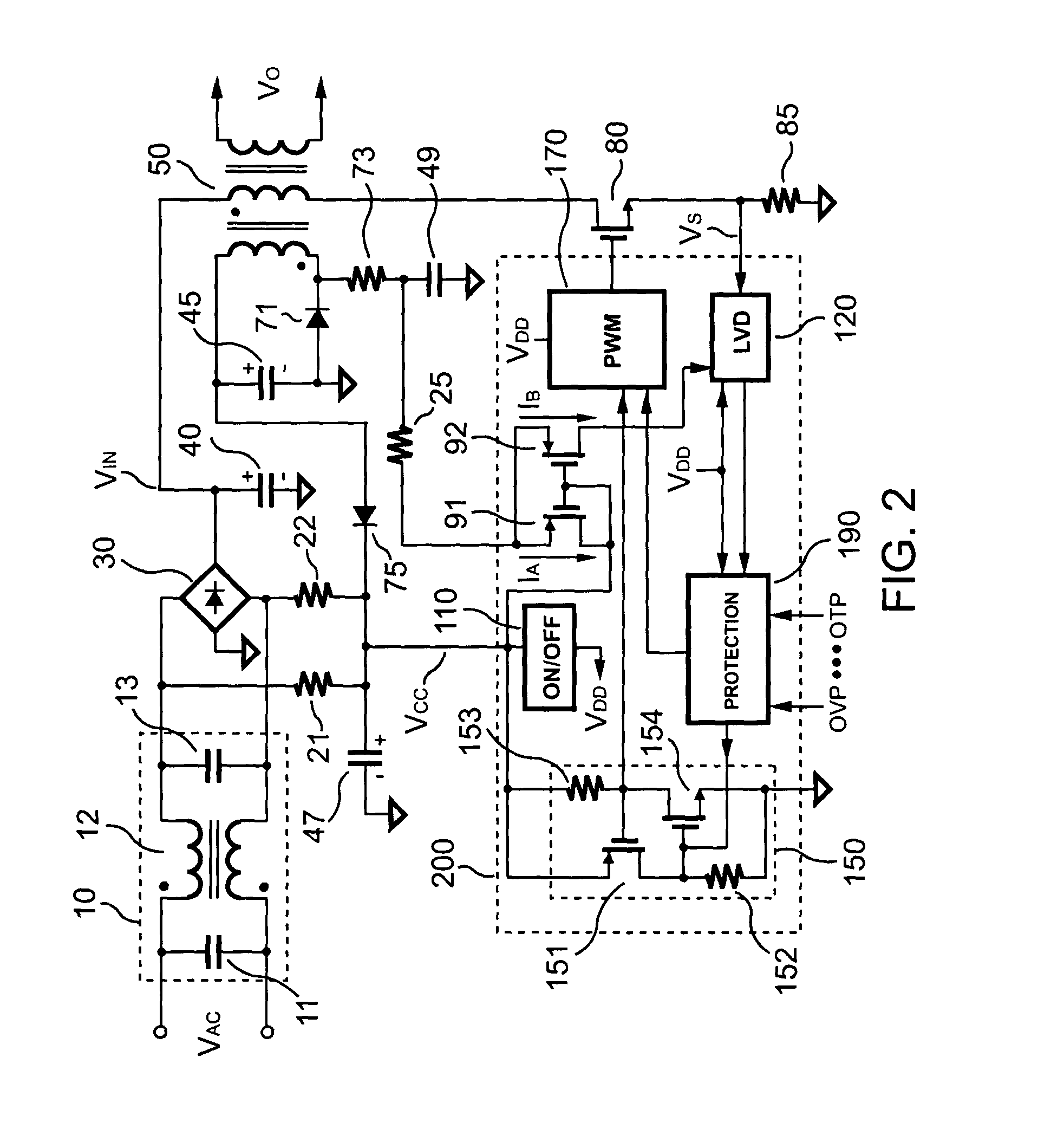
[0023]FIG. 2 shows an input circuit of a power supply according to the present invention. An AC input source VAC is supplied to a first AC input and a second AC input of a bridge rectifier 30 via an EMI filter 10. An output of the bridge rectifier 30 is connected to an input capacitor 40 to produce a DC input voltage VIN. A transformer 50 is coupled to the input capacitor 40. A power transistor 80 is used for switching the transformer 50.

[0024] The power supply includes a control-circuit 200, which comprises an ON / OFF circuit 110, a line-voltage detector (LVD) 120, a latch circuit 150, a PWM circuit 170, a protection circuit 190, and two mirror transistors 91 and 92. A supply voltage VCC supplies power to the control-circuit 200. The ON / OFF circuit 110 starts up PWM operation whenever the supply voltage VCC exceeds a start-threshold voltage. When the supply voltage VCC drops below a stop-threshold voltage, the ON / OFF circuit 110 will disable PWM operation.

[0025] The PWM circuit 17...


PUM


Abstract

A switching power supply control-circuit according to the present invention uses bleeding resistors to charge a start-up capacitor and discharge an EMI filter. No extra discharge device is needed to accelerate the discharge of the input capacitor, since the start-up capacitor is charged up by the AC input source. A latch circuit of the power supply can be quickly reset after the AC input source is shut off. After the control-circuit begins to operate, the auxiliary winding of the transformer will power the control-circuit. To further reduce power consumption, the auxiliary winding generates a bias voltage to enable line-voltage detection. This allows the power supply to perform line-voltage detection and startup, without having to connect resistors or transistors to the input capacitor.

Description

BACKGROUND OF THE INVENTION [0001] 1. Field of the Invention [0002] The present invention generally relates to power supplies. More particularly, the present invention relates to the start-up circuit of a switching power supply. [0003] 2. Description of the Prior Art [0004] Switching mode power supplies have largely replaced linear transformers and linear power supplies. Switching mode power supplies have grown in popularity, because they are more cost effective than linear power supplies. Furthermore, they offer several other advantages over linear power supplies, including reduced size, improved efficiency, and higher performance. [0005] However, the start-up circuitry commonly used by switching mode power supplies can be substantially improved. [0006] Several passive start-up devices known in the prior arts include U.S. Pat. No. 5,200,886 (Karl Schwarz, Horst Bartussek, Helmut Rettenmaier), U.S. Pat. No. 5,262,933 (Chen Shyi-Hon), U.S. Pat. No. 5,452,195 (Steffen Lehr, Volker Nei...

Claims


Application Information

Patent Timeline
IPC IPC(8): H02M1/00H02M1/36H02M1/44H02M3/156
CPCH02M1/36H02M1/44Y10S323/901H02M2001/0006H02M3/156H02M1/0006
Inventor YANG, TA-YUNGLIN, SONG-YILIN, CHIEN YUAN
Owner SYST GEN
Why Eureka
Try Eureka