Temperature detecting circuit for controlling a self-refresh period of a semiconductor memory device

Active Publication Date: 2005-03-10
TAIWAN SEMICON MFG CO LTD
View PDF2 Cites 23 Cited by
  • Summary
  • Abstract
  • Description
  • Claims
  • Application Information

AI Technical Summary

Benefits of technology

Accordingly, an object of the present invention is to provide an apparatus for controlling the refresh perio

Problems solved by technology

As time passes, the electric charge stored in that capacitor leaks through a substrate or the like, making it difficult to permanently store data.
However, when the temperature is lower, the self-refresh function in a DRAM

Method used


Image

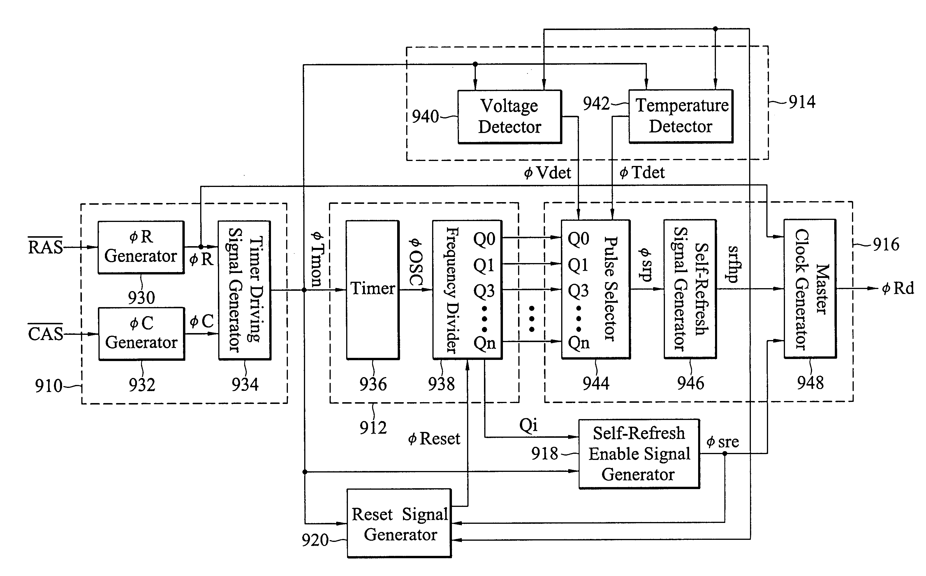
  • Temperature detecting circuit for controlling a self-refresh period of a semiconductor memory device
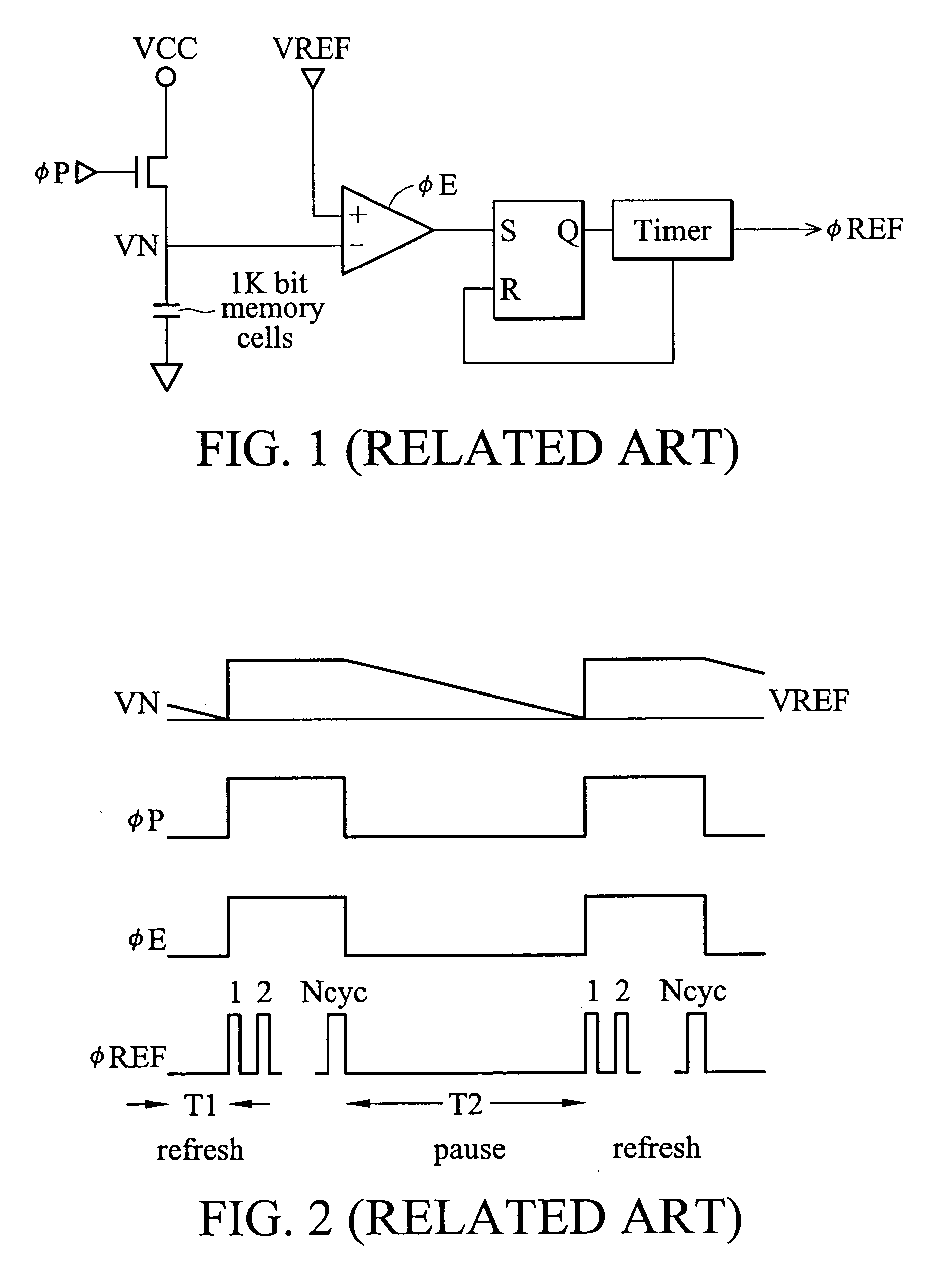
  • Temperature detecting circuit for controlling a self-refresh period of a semiconductor memory device
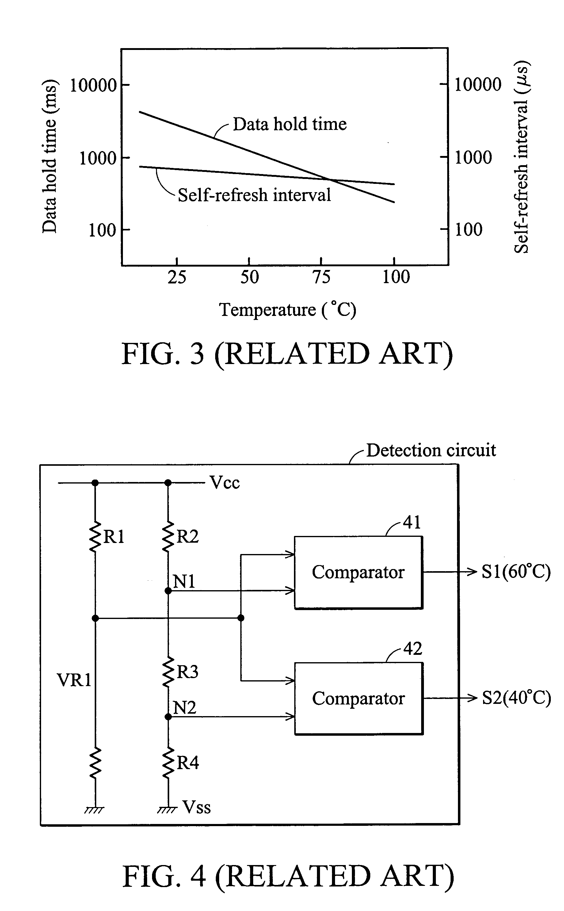
  • Temperature detecting circuit for controlling a self-refresh period of a semiconductor memory device

Examples


Embodiment Construction

Disclosed herein are systems and methods for a temperature detecting circuit for controlling a self-refresh period of a semiconductor memory device. To facilitate description of the inventive system, an example system that can be used to implement the temperature detecting circuit is discussed with reference to the figures. Although this system is described in detail, it will be appreciated that this system is provided for purposes of illustration only and that various modifications are feasible without departing from the inventive concept. After the example system has been described, an example of operation of the system will be provided to explain the manner in which the system can be used to provide a temperature detecting circuit.

FIG. 8 shows a temperature detecting circuit according to a preferred embodiment of the invention. The circuit preferably includes a voltage comparator composed of seven transistors 811˜817 and three voltage dividers respectively composed of resistors...


PUM


Abstract

Systems for providing a temperature detecting circuit includes seven transistors and six resistors. In a preferred embodiment, one of the seven transistors is configured as an enabling element and the others form two comparators. The six resistors form three voltage dividers with output varying based upon changing temperature. Two comparators are included that sense the difference between the outputs of two of the voltage dividers, and generate a corresponding 2-bit detection signal by which the refresh period is determined. Other systems and methods are also provided.

Description

BACKGROUND The present invention relates to a temperature detecting circuit and particularly to a temperature detecting circuit for controlling a self-refresh period of a semiconductor memory device. A dynamic random access memory (hereinafter called “DRAM”) stores data by storing an electric charge in a memory cell capacitor. As time passes, the electric charge stored in that capacitor leaks through a substrate or the like, making it difficult to permanently store data. It is, therefore, necessary to perform a refresh operation, that is, continuously rewrite the data at a pre-determined interval. Generally, the refresh operation is achieved by applying an external control signal. A refresh operation which is achieved by an internal control signal generated inside the memory is called a “self-refresh function.” With the recent expansion of applications for DRAM, the demand for DRAM for use with devices or equipment with a battery-backup function has increased. Thus, it is desirab...

Claims


Application Information

Patent Timeline
IPC IPC(8): G11C11/406
CPCG11C11/406G11C2211/4061G11C11/40626
Inventor CHOU, CHUNG-CHENG
Owner TAIWAN SEMICON MFG CO LTD
Why Eureka
Try Eureka