Magnetic thin film and method of manufacturing the same

a thin film and magnetic technology, applied in the field of magnetic thin film, can solve the problems of poor recording characteristics, poor soft magnetism, and poor stress of plated film, and achieve the effects of high coercive force, good soft magnetism, and high saturation magnetic flux density

Inactive Publication Date: 2005-03-10
FUJITSU LTD
View PDF9 Cites 14 Cited by
  • Summary
  • Abstract
  • Description
  • Claims
  • Application Information

AI Technical Summary

Benefits of technology

[0023] In the present invention, the magnetic thin film comprises the FeCo/NiFe base layer and the FeCo plated layer formed on the base layer. Therefore, the magnetic thin film has high saturation magnetic flux density and good soft magnetism, so that it can be a proper magnetic thin film of the magnetic head. The FeCo plated layer can be thick, the magnetic thin film ...

Problems solved by technology

If the coercive force of the material is great, current responsibility is low when the magnetic head is driven, so that recording characteristics are made worse.
Especially, hysteresis loss, which causes problems in a high frequency band, is caused, so that the recording characteristics in the high frequency band are made worse.
However, stress of the plated film is great, so thickness of the plated film m...

Method used


Image

  • Magnetic thin film and method of manufacturing the same
  • Magnetic thin film and method of manufacturing the same
  • Magnetic thin film and method of manufacturing the same

Examples


Embodiment Construction

[0040] Preferred embodiments of the present invention will now be described in detail with reference to the accompanying drawings.

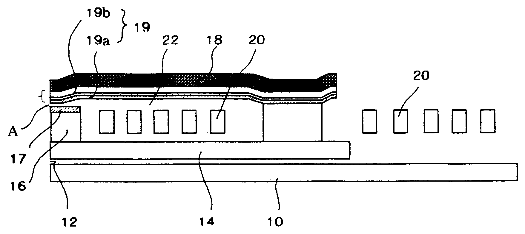
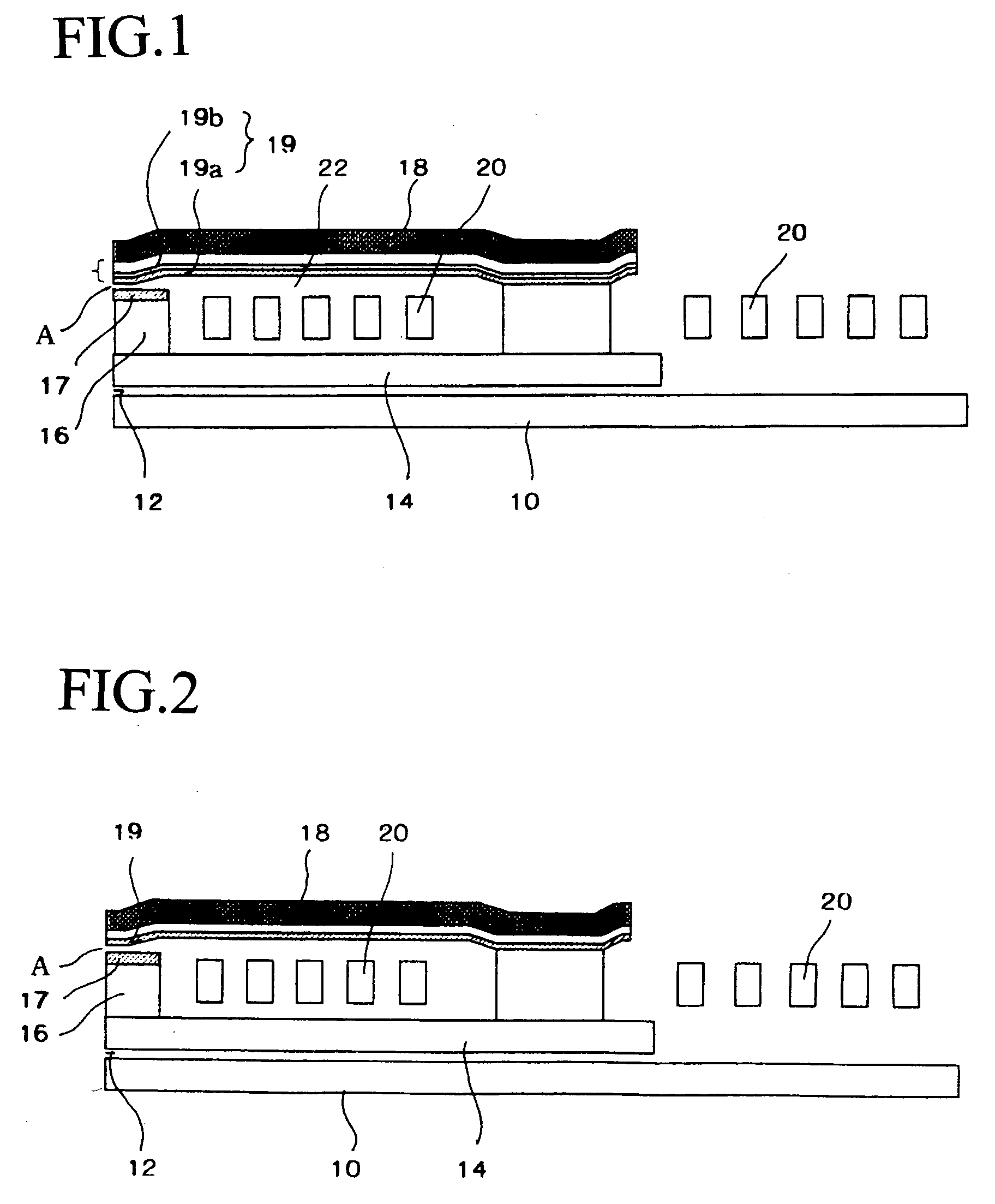
[0041]FIG. 1 is a schematic sectional view of a magnetic head of an embodiment. The magnetic head includes: a lower shielding layer 10; an MR head 12; a lower magnetic pole 14; an upper magnetic pole 18; and coils 20. The basic structure of the magnetic head is similar to the conventional one shown in FIG. 2.

[0042] The feature of the magnetic head of the present embodiment is a magnetic thin film 19, which is formed on the upper magnetic pole 18 and which faces a write-gap A. The magnetic thin film 19 comprises: a base layer 19a made of piled FeCo / NiFe; and a plated layery 19b made of FeCo.

[0043] Since the plated layer 19b made of FeCo is formed on the base layer 19 are made of FeCo / NiFe, the magnetic thin film 19 has high saturation magnetic flux density and a low coercive force. By employing the magnetic thin film 19 as at least a part of magnetic po...


PUM


Abstract

The magnetic thin film has high saturation magnetic flux density and superior soft magnetic characteristics. The magnetic thin film of the present invention comprises: a base layer being made of FeCo/NiFe; and a plated layer being formed on the base layer, the plated layer being made of FeCo.

Description

BACKGROUND OF THE INVENTION [0001] The present invention relates to a magnetic thin film, a method of manufacturing the magnetic thin film, and a magnetic head including the magnetic thin film, more precisely relates to a magnetic thin film, which is formed by plating and which has high saturation magnetic flux density and a low coercive force, a method of manufacturing the same, and a magnetic head including the same. [0002] A schematic sectional view of a conventional magnetic head of a magnetic disk drive unit is shown in FIG. 2. A symbol 12 stands for an MR head; a symbol 10 stands for a lower shielding layer of the MR head 12; and a symbol 14 stands for an upper shielding layer 14 of the MR head 12. The upper shielding layer 14 acts as a lower magnetic pole of a write-head section. [0003] The lower magnetic pole 14 has an end magnetic pole section 16, and a surface of the end magnetic pole section 16 is covered with a magnetic layer 17. An upper magnetic pole 18 is provided to ...

Claims


Application Information

Patent Timeline
IPC IPC(8): G11B5/147G11B5/187G11B5/31H01F10/16H01F41/18H01F41/26
CPCG11B5/3113G11B5/3163Y10T428/115Y10T428/265Y10T428/1193Y10T428/1186
Inventor MIYAKE, YUKOKANEKO, DAIJU
Owner FUJITSU LTD
Why Eureka
Try Eureka