Fuel storage and dispensing system

a technology of fuel storage and dispensing system, which is applied in the direction of membranes, packaging goods, separation processes, etc., can solve the problems of significant emission of nozzles employed in vacuum assist systems are not without faults, and the coaxial design of the nozzle is prone to dripping, so as to reduce the emission of harmful volatile organic compounds into the environment, reduce fugitive emissions, and reduce fugitive emissions

Inactive Publication Date: 2005-03-17
VAPOR SYST TECH
View PDF38 Cites 19 Cited by
  • Summary
  • Abstract
  • Description
  • Claims
  • Application Information

AI Technical Summary

Benefits of technology

[0006] The present invention meets the above-mentioned needs by providing a fuel storage and dispensing system, a fuel dispensing nozzle and spout assembly, a pressure relief assembly, a vapor recovery boot, and a Venturi shut-off assembly for a fuel dispensing nozzle and spout. Although the present invention is not limited to specific advantages or functionality, it is noted that each embodiment of the instant invention is effective in reducing the emission of volatile organic compounds into the environment both during fueling, as well as during storage of gasoline.
[0024] The boot can further comprise an annular rib positioned on the distal end of the boot. The annular rib is configured to fit against the surface proximate the fuel tank inlet pipe of the vehicle during fueling. The boot is configured to maintain a sufficient level of vacuum within the fuel storage and dispensing system to ensure adequate vapor recovery and accurate system diagnostics. The boot is positioned surrounding the rigid, fuel dispensing spout and defines an annular passage configured for receiving fuel vapor displaced from the fuel tank inlet pipe of the vehicle during fueling. The annular passage is in communication with the vapor return opening in the spout attachment end of the fuel dispensing nozzle. The boot is configured to prevent fresh air from entering the vapor return opening in the spout attachment end of the fuel dispensing nozzle.
[0030] Accordingly, it is a feature of the present invention to provide a fuel storage and dispensing system which is effective in reducing fugitive emissions. It is also a feature of the present invention to provide a fuel dispensing nozzle and spout assembly, and a vapor recovery boot assembly, which is effective in reducing fugitive emissions. It is also a feature of the present invention to provide a pressure relief assembly and a Venturi shut-off assembly, which both further reduce the emission of harmful volatile organic compounds into the environment. These and other features and advantages of the invention will be more fully understood from the following detailed description taken together with the accompanying drawings. It is noted that the scope of the appended claims is defined by the recitations therein and not by the specific discussion of features and advantages set forth in the present description.

Problems solved by technology

However, the nozzles employed in vacuum assist systems are not without faults.
The coaxial design of the nozzle is prone to dripping once fueling is complete and the nozzle is discharged from the vehicle tank inlet pipe.
Such dripping can lead to significant emission of volatile organic compounds (“VOC”) into the environment.

Method used


Image

  • Fuel storage and dispensing system
  • Fuel storage and dispensing system
  • Fuel storage and dispensing system

Examples


Embodiment Construction

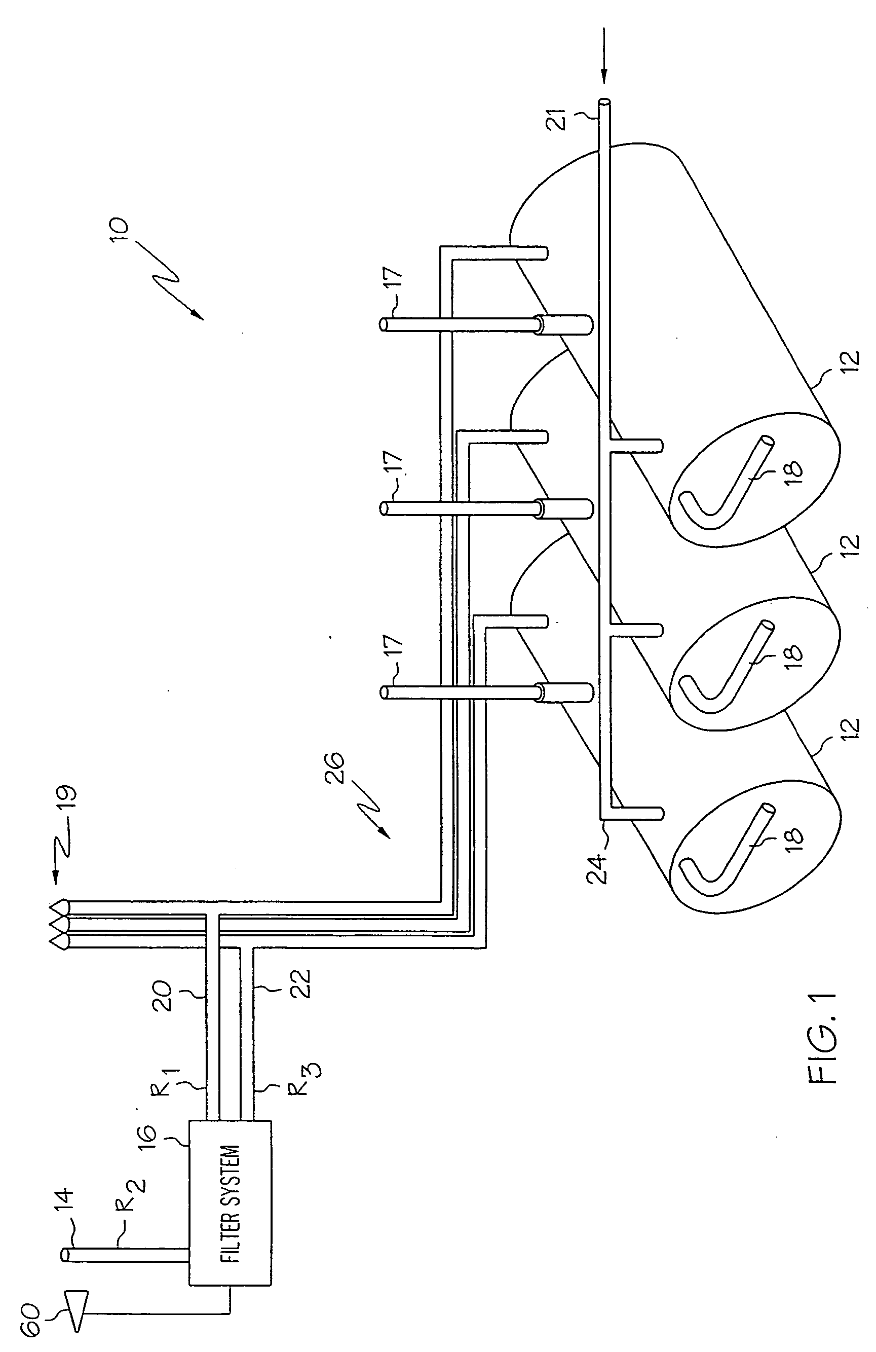
[0049] Referring initially to FIG. 1, a fuel storage and dispensing system 10 according to the present invention is illustrated. The system 10 is operated below atmospheric pressure and comprises at least one storage tank 12, an air exhaust port 14, and a filter system 16. The storage tank 12 is coupled to a fuel inlet port 17, a fuel delivery port 18, a pressure relief port 19, a fluid vent port 20, a vapor return port 21, a pollutant return port 22, vapor pressure equalization piping 24, and vent piping 26. A fuel dispensing nozzle of the fuel storage and dispensing system 10 (not shown) is arranged to return fuel vapor to the storage tank 12 via the vapor return port 21.

[0050] As will be appreciated by those practicing the present invention, the specifics of the design of the storage tank 12, fuel inlet port 17, fuel delivery port 18, pressure relief port 19, fluid vent port 20, vapor return port 21, pollutant return port 22, vapor pressure equalization piping 24, and vent pipin...


PUM

PropertyMeasurementUnit
volumetric fluid flow rate R2aaaaaaaaaa
volumetric fluid flow rateaaaaaaaaaa

Abstract

A fuel storage and dispensing system is provided that is effective in reducing the emission of harmful volatile organic compounds. In accordance with one embodiment of the present invention, a fuel storage and dispensing system is provided comprising at least one storage tank, an air exhaust port, at least one fuel dispenser, a fuel dispensing nozzle, a rigid, fuel dispensing spout, a boot, a pressure relief chamber, a filter system, and at least one pump. The rigid, fuel dispensing spout further defines a non-coaxial fuel tube. The boot is configured to maintain a sufficient level of vacuum within the fuel storage and dispensing system. The boot is further configured to prevent fresh air from entering the fuel dispensing nozzle. The present invention also includes additional embodiments including a pressure relief chamber that is effective in compensating for high temperature pressure build-up in a vapor assist hose, a fuel dispensing nozzle and spout assembly, a vapor recovery boot assembly, and a Venturi shut-off assembly for a fuel dispensing nozzle and spout.

Description

CROSS-REFERENCE TO RELATED APPLICATIONS [0001] This is a divisional of U.S. patent application Ser. No. 10 / 335,090, filed Dec. 31, 2002 for FUEL STORAGE AND DISPENSING SYSTEM which in turn claims the benefit of U.S. Provisional Patent Application Ser. No. 60 / 354,703, filed Feb. 6, 2002 for DRIPLESS NOZZLE AND BOOT ASSEMBLY FOR VACUUM-INDUCED VAPOR RECOVERY, and is related to U.S. patent application Ser. No. 09 / 963,107, filed Sep. 24, 2001 for DIAGNOSTIC FUEL STORAGE SYSTEM, which is related to U.S. patent application Ser. No. 09 / 440,520, filed Nov. 15, 2000 for FUEL STORAGE SYSTEM WITH VENT FILTER ASSEMBLY (now U.S. Pat. No. 6,293,996) and Ser. No. 09 / 036,119, filed Mar. 6, 1998 for FUEL STORAGE SYSTEM WITH VENT FILTER ASSEMBLY (now U.S. Pat. No. 5,985,002). This application is also related to U.S. patent application Ser. No. 09 / 796,108, filed Feb. 28, 2001 for VAPOR RECOVERY LINE DIAGNOSTICS (now U.S. Pat. No. 6,360,789). Each of the above-identified U.S. patent properties is hereb...

Claims


Application Information

Patent Timeline
Patent Type & Authority Applications(United States)
IPC IPC(8): B01D53/22B67D7/04B67D7/54
CPCB01D53/22B01D63/06B67D7/54B67D7/0476B01D2313/18B67D2007/545
Inventor WALKER, GLENN K.GRANTHAM, RODGER P.ALLEN, KEN
Owner VAPOR SYST TECH
Why Eureka
Try Eureka