System and method for maintaining a vehicle at zero speed on a graded surface

a technology of zero speed and graded surface, applied in the field of vehicle control, can solve the problems of excessive heat generation, damage to powertrain components, and reduce the lifetime of the powertrain and/or its components

Inactive Publication Date: 2005-03-17
GM GLOBAL TECH OPERATIONS LLC
View PDF8 Cites 18 Cited by
  • Summary
  • Abstract
  • Description
  • Claims
  • Application Information

AI Technical Summary

Benefits of technology

[0007] In one embodiment, and by way of example only, a method of maintaining a vehicle having a powertrain system and a brake system at a substantially zero speed on a graded surface includes determining that the powertrain system is supplying a hold torque. The hold torque has a magnitude sufficient to substantially maintain the vehicle at a substantially zero speed on the graded surface. A brake torque at a magnitude at least equivalent to the hold torque is automatically applied from the vehicle brake system to thereby maintain the vehicle at the substantially zero speed.
[0008] In another exemplary embodiment, a control system for maintaining a vehicle at a substantially zero speed on a graded surface includes a powertrain controller and a brake controller. The powertrain controller is adapted to receive one or more signals representative of vehicle powertrain system status and is operable, in response thereto, to determine that the powertrain system is supplying a hold torque and to issue a brake apply request signal in response to this determination. The hold torque has a magnitude sufficient to substantially maintain the vehicle at a substantially zero speed on the graded surface. The brake controller is coupled to receive the brake apply request signal from the powertrain controller and is operable, in response thereto, to issue a vehicle brake apply command to a vehicle brake system to thereby cause the vehicle brake system to apply a brake torque at a magnitude at least equivalent to the hold torque, whereby the vehicle is substantially maintained at the substantially zero speed.
[0009] In yet another exemplary embodiment, an automobile includes a powertrain system, a powertrain controller, a brake controller, and a brake system. The powertrain system includes an engine that is operable to supply an engine torque, and a transmission that is coupled to receive the engine torque and is operable to selectively transmit the received engine torque to one or more vehicle wheels. The powertrain controller is coupled to receive one or more signals representative of vehicle powertrain system status and is operable, in response thereto, to determine that the powertrain system is supplying a hold torque and to issue a brake apply request signal in response to this determination. The hold torque has a magnitude sufficient to substantially maintain the vehicle at a substantially zero speed on the graded surface. The brake controller is coupled to receive the brake apply request signal from the powertrain controller and is operable, in response thereto, to issue a vehicle brake apply command. The brake system is coupled to receive the vehicle brake apply command signal from the brake controller and is operable, in response thereto, to apply a brake torque to the vehicle wheels at a magnitude at least equivalent to the hold torque, whereby the vehicle is substantially maintained at the zero speed. The brake command issued by the brake controller causes the brake system to increase the brake torque to at least the hold torque at a first rate, and the powertrain controller, in response to a communication from the brake controller, causes the powertrain system to decrease the torque it supplies at a second rate.

Problems solved by technology

However, this method can result in powertrain component damage and / or reduce the lifetime of the powertrain and / or its components.
For example, the torque converter in an automatic transmission-equipped vehicle, or the clutch in case of a manual transmission, can generate heat that may be of a magnitude sufficient to cause damage to the powertrain if this condition is maintained for a relatively long period of time.
Moreover, in a vehicle powered by an electric motor, the motor may draw a so-called “stall current,” which can result in excessive heat generation, unnecessary power consumption, and potential component damage.

Method used


Image

  • System and method for maintaining a vehicle at zero speed on a graded surface
  • System and method for maintaining a vehicle at zero speed on a graded surface
  • System and method for maintaining a vehicle at zero speed on a graded surface

Examples


Embodiment Construction

[0014] The following detailed description is merely exemplary in nature and is not intended to limit the invention or the application and uses of the invention. Furthermore, there is no intention to be bound by any theory presented in the preceding background or the following detailed description.

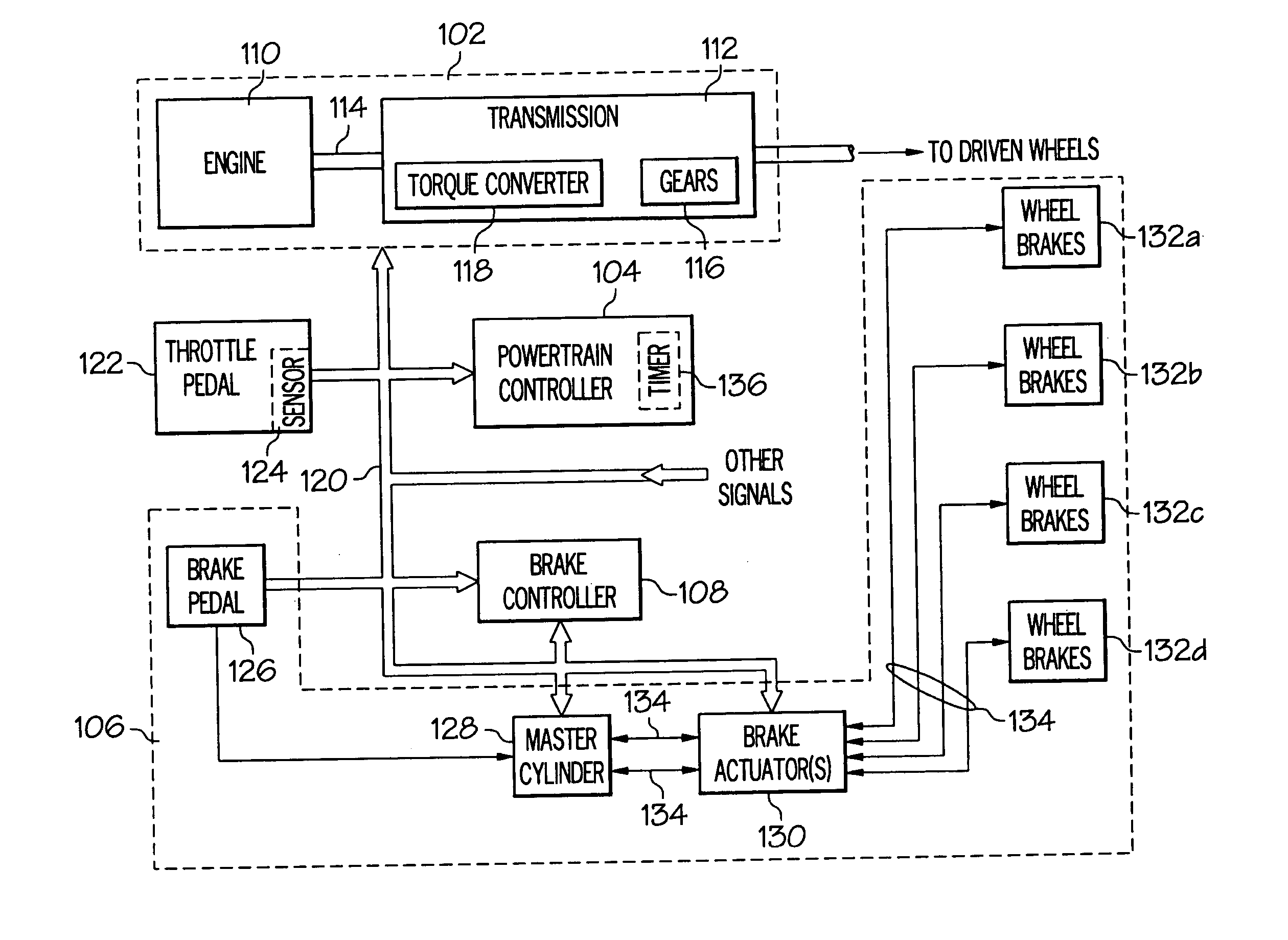
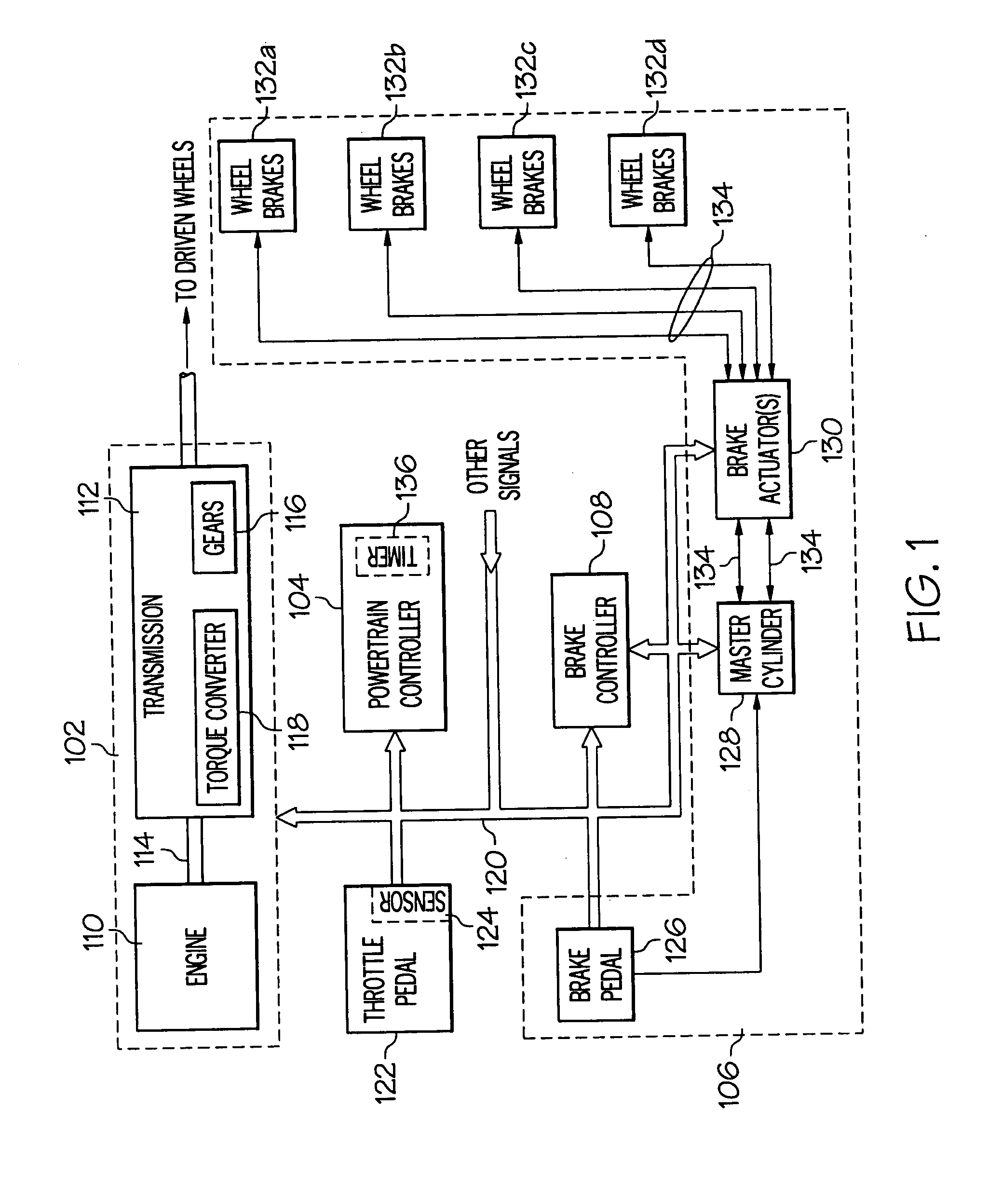
[0015] An exemplary embodiment of a vehicle system 100 is illustrated in FIG. 1. The vehicle system 100 includes a powertrain 102, a powertrain controller 104, a vehicle brake system 106, and a brake controller 108. The powertrain system 102 includes an engine 110 and a transmission 112. The engine 110 is the prime mover of the vehicle system 100 and generates the torque necessary to accelerate the vehicle system 100 to a desired velocity, and to maintain the vehicle at this desired velocity. It should be appreciated that the engine 110 may be any one of numerous engine designs including, but not limited to, any one of numerous diesel or internal combustion engine designs, any one of numer...


PUM


Abstract

Methods and apparatus are provided for determining when vehicle powertrain torque is being used to substantially maintain a vehicle at a substantially zero speed on a graded surface, and to shift the supplied torque from the powertrain to another vehicle system or component. A vehicle controller determines that the powertrain system is supplying a hold torque, which has a magnitude sufficient to substantially maintain the vehicle at a substantially zero speed on the graded surface. A brake torque at a magnitude at least equivalent to the hold torque is automatically applied from the vehicle brake system to thereby maintain the vehicle at the substantially zero speed. Thus, the powertrain system can remove the torque it is supplying to hold the vehicle at the substantially zero speed.

Description

FIELD OF THE INVENTION [0001] The present invention generally relates to vehicle control and, more particularly, to a system and method for maintaining a vehicle at a substantially zero speed on a graded road or other surface. BACKGROUND OF THE INVENTION [0002] When a vehicle is on a graded surface, the vehicle experiences a gravitational force component that acts to move the vehicle in a generally downward direction, which may be in a direction opposite to the direction the vehicle driver wants the vehicle to move. For example, if the vehicle is moving up a graded surface or hill, in either a forward or a rearward direction, a gravitational force component will act in the opposite direction, tending to counteract the torque supplied by the vehicle powertrain. Thus, as many vehicle drivers have experienced, when moving a vehicle up a graded surface, the torque output from the vehicle powertrain typically needs to be increased in order to maintain the vehicle at the same speed on the...

Claims


Application Information

Patent Timeline
Patent Type & Authority Applications(United States)
IPC IPC(8): B60T7/12B60W10/06B60W10/08B60W30/18
CPCB60T7/122B60T2201/06B60W10/06B60W10/08Y10T477/644B60W30/18118Y10T477/814Y10T477/745B60W10/184
Inventor KINSER, CHRISTOPHER A.CLAYPOLE, GEORGE M.CHHAYA, SUNIL M.
Owner GM GLOBAL TECH OPERATIONS LLC
Why Eureka
Try Eureka