Motor control method and control device

a control method and motor technology, applied in the direction of electric programme control, program control, instruments, etc., can solve the problems of slow driving speed of the driving target, inability to achieve stable operation, and longer time for generating necessary torque, etc., to achieve the effect of driving stably

Active Publication Date: 2005-03-17
BROTHER KOGYO KK
View PDF13 Cites 20 Cited by
  • Summary
  • Abstract
  • Description
  • Claims
  • Application Information

AI Technical Summary

Benefits of technology

[0038] According to the motor control device of the present invention constituted as above, the driving targe...

Problems solved by technology

However, with a control method as described in FIG. 71A wherein a PWM value is set to a specified initial value (start_pwm1) at the time of every encoder edge detection, stable operation (driving) may not be achieved when load on a DC motor fluctuates.
Thereby, time for generation of necessary torque becomes longer, and consequently the driving velocity of the driving target becomes slow.
When the load becomes...

Method used


Image

  • Motor control method and control device
  • Motor control method and control device
  • Motor control method and control device

Examples


first embodiment

[0115] [First Embodiment]

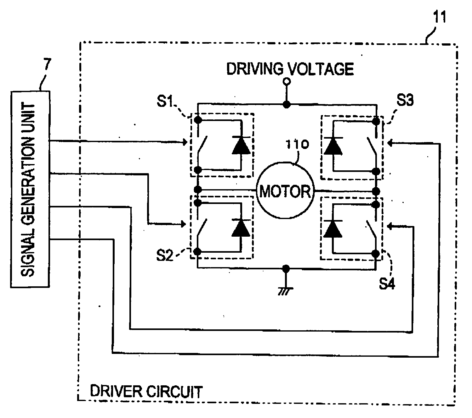
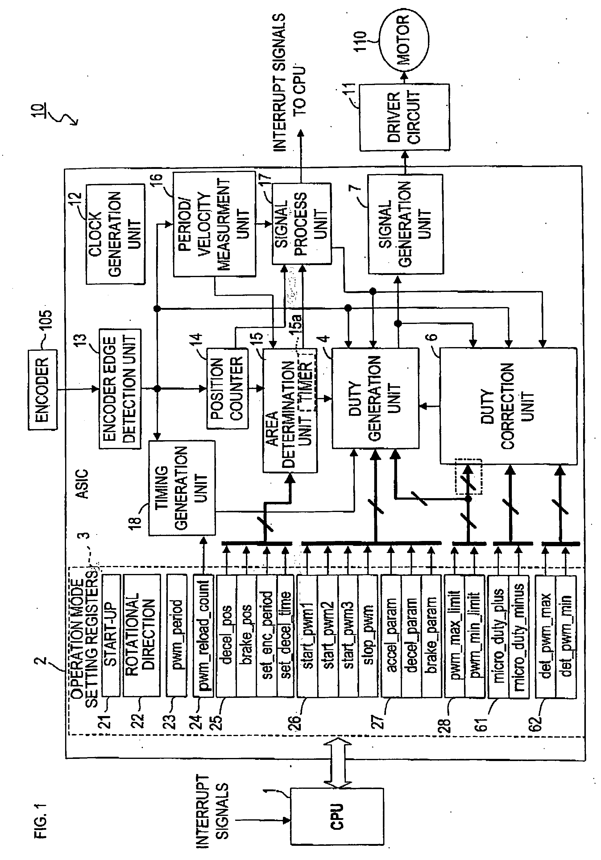
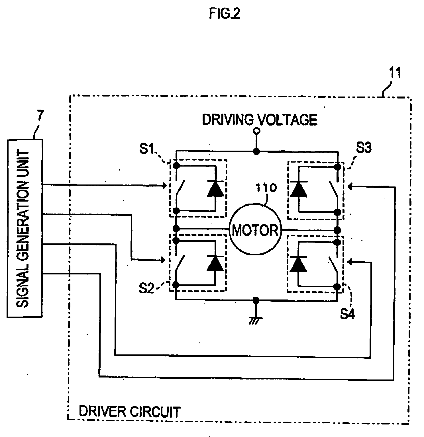
[0116] A motor control device 10 in FIG. 1 is installed in an inkjet printer, for example, described in FIG. 70 in order to control a (DC) motor 110 which drives a carriage 102. Amongst all types of control on the motor 110, minimal velocity control, which is conducted when the carriage 102 moves to a right side and capping of the carriage 102 is conducted in a standby area after recording is completed, will be described in the present embodiment.

[0117] The minimal velocity control of the motor 110 conducted by the motor control device 10 of the present embodiment is basically the same as the control method described in FIGS. 71A and 71B. When driving is initiated, a PWM value is set to a predetermined start PWM value (start_pwm1) at a time of driving initiation, subsequently the PWM value is increased by a constant PWM increment value (accel_param) during driving in every constant period Tp. When an encoder edge is detected and encoder edge signals (enc_tr...

second embodiment

[0194] [Second Embodiment]

[0195]FIG. 14 is a block diagram showing a schematic structure of a motor control device 140 of the second embodiment. In the aforementioned first embodiment, the initial PWM value after reset at the time of encoder edge detection is not constantly set to start_pwm1, but changed corresponding to the PWM value when the edge is detected. The distinct difference of the second embodiment from the first embodiment is that a rate of change to increase a PWM value in constant period Tp is not fixed at accel_param / Tp, but the rate is changed at the time of every encoder edge detection corresponding to an edge interval (enc_period), which is time between a previous edge detection and a current edge detection.

[0196] Specifically, in the present embodiment, a PWM increment value (a_param) during driving is not fixed at the initial value of the PWM increment value (accel_param) during driving, but changed corresponding to an edge interval (enc_period). The following d...

third embodiment

[0319] [Third Embodiment]

[0320]FIG. 41 shows a schematic structure of a motor control device 810 of the present embodiment. In the present embodiment, in order to control the motor 110 (and further controlling the carriage 102) upon capping, correction data (hereinafter, referred to as “initial PWM value”) for changing the start PWM value (start_pwm1) into a proper value is set in advance in accordance with the position of the carriage 102 (more particularly, based on the load of the motor 110 at the position), based on the assumed fluctuation in the motor 110 load during the drive of the carriage 102. Furthermore, the initial PWM correction value for each position is stored in the profile storage unit 9 as an initial PWM correction value profile (cmp_array). This “position” is a position where an encoder edge is detected. In other words, an arrangement of the respective initial PWM correction values corresponding to the respective positions where encoder edges are detected is profi...


PUM


Abstract

When motor drive is initiated, firstly a PWM value at time of driving initiation is set to an initial setting value start_pwm1, and gradually increased by a specified amount in specified period. When an encoder edge is detected, the PWM value is reset to the initial setting value, and increased again in the same manner. From second edge detection, next PWM initial value is set corresponding to a PWM value at the time of edge detection. If the PWM value at the time of edge detection is larger than det_pwm_max owing to load on the motor becoming large and thereby driving velocity becoming slower, a PWM value which is larger than previous PWM initial value is set as a new PWM initial value. The driving target can be driven stably irrelevant to fluctuation of the load on the motor.

Description

(1) FIELD OF THE INVENTION [0001] This invention relates to a control method of a motor and a control device, especially to motor control wherein driving force of a motor is increased from an initial value by a specified amount in a specified period while a driving target is driven for a specified amount. (2) BACKGROUND ART [0002] Conventionally, a closed loop control method, such as speed feed back control or position feed back control, is well known as one of control methods of DC and AC motors. Generally, the above mentioned closed loop control is conducted by using an encoder or the like, in order to detect rotational amount of a motor, or driving amount of the driving target. Based on information from the encoder, respective feed back controls mentioned above are conducted. [0003] However, when these feed back controls with an encoder are applied to a case wherein a driving target is driven at minimal velocity (that is, in case a motor is rotated at minimal velocity), it is pos...

Claims


Application Information

Patent Timeline
IPC IPC(8): H02P23/00H02P27/08
CPCH02P27/08H02P23/0063H02P23/20
Inventor AKIYAMA, SHIGEKI
Owner BROTHER KOGYO KK
Why Eureka
Try Eureka