Spectrometer

a spectrometer and spectrometer technology, applied in the field of spectrometry, can solve the problems of high cost of such spectrometers with fixed gratings, high cost of such spectrometers, and additional costs per slave module, and achieve the effect of satisfying spectral resolution, satisfying spectral detection range, and low cos

Inactive Publication Date: 2005-03-17
FRAUNHOFER GESELLSCHAFT ZUR FOERDERUNG DER ANGEWANDTEN FORSCHUNG EV
View PDF0 Cites 13 Cited by
  • Summary
  • Abstract
  • Description
  • Claims
  • Application Information

AI Technical Summary

Benefits of technology

[0012] It is the object of the present invention to provide a spectrometer as well as a method for determining a spectral distribution, so that with relatively low cost and despite miniaturization both a satisfying spectral resolution and a satisfying spectral detection range and / or a high mechanical stability can be obtained.

Problems solved by technology

For so-called low-cost applications, devices of the type of FIG. 3 are too expensive and too costly due to their expensive mechanical control of the quasi-static movement of the grating 900.
Although the prices of such spectrometers with fixed grating are low, it is a disadvantage of these fixed grating systems, that the wavelength range detected by the photodiode line 922 as well as the spectral resolution are set during production and are thus invariable.
Thereby, however, additional costs per slave module occur.
One specific problem in the design of miniature spectrometers is that the available space is limited, whereby, on the one hand, the detectable detection range and, on the other hand, the obtainable resolution is limited.
If, for example, by using a photodiode line with fixed density and by considering maximum dimensions, a spectrometer of the type of FIG. 4 is designed for high resolution, this is performed at the cost of the detectable spectral range, and conversely, if the spectrometer is designed for a large spectral range, a poorer resolution results.
This resolution is sufficient for many applications, but the resulting spectral detection range is too small for many applications, since, for evaluation, usually two or more spectral lines of the spectrum to be examined have to be taken into consideration and thus have to be within the detection range.
Alternatively, if the spectrometer is designed for a lower resolution, a larger range of, for example, 600 nm can be achieved, such that it would be sufficient for the spectroscopy across the visible spectral range, i.e. for the wavelengths of 400 nm to 800 nm, but the resulting resolution of 2 nm provides only a very poor quality.
In the above conventional spectrometer solution of FIG. 3, there are problems in a miniaturization with regard to the producible deflections of the grating, which again limits the spectral detection range.
Further, the expensive control for the quasi-static movement prevents a cost-effective realization.

Method used


Image

  • Spectrometer
  • Spectrometer
  • Spectrometer

Examples


Embodiment Construction

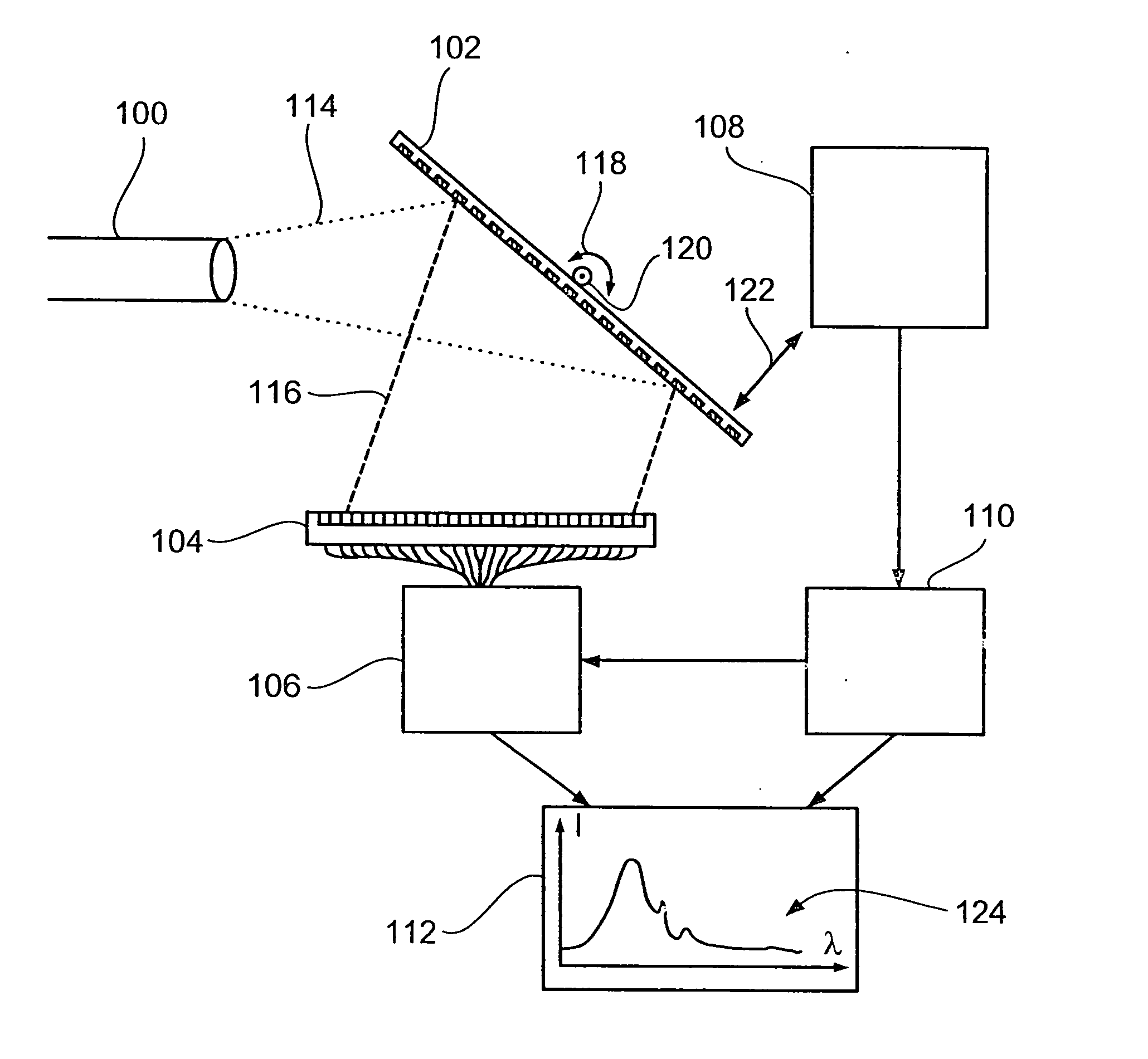
[0024] First, with regard to FIG. 1, a simplified representation of a spectrometer is described according to an embodiment of the present invention. The spectrometer of FIG. 1 comprises a movable grating 10, which receives an incident light beam 12, whose spectral distribution is to be determined. The movable grating 10 is designed as vibratably suspended mirror with a grating structure and is, in the present case, vibratably rotatably mounted and suspended, respectively, around an axis 14. The suspension (not shown) of the movable grating 10 defines a restoring force, which depends on the deflection of the movable grating 10 from the resting position. The suspension consists, for example, of two ridges, which support a frame of the grating (in the FIG. from the top and the bottom) along the axis 14 at two opposing side centers, wherein the restoring force corresponds to the torsion force, which is established by torsion of the ridges during vibration. Further, a different suspensio...


PUM


Abstract

The present invention is based on the knowledge that the advantages of a moveable dispersive element with regard to the simple detector element and the adjustability of the measurement range and the resolution can also be used in a miniaturization of a spectrometer, when the dispersive element is operated generally in resonance instead by a quasistatic drive. A proposed spectrometer comprises a vibratably suspended dispersive element for spectrally decomposing a light beam, whose spectral distribution is to be determined, into spectral components, a means for putting the vibratably suspended dispersive element into a vibration with a frequency, which is in such a ratio to the natural frequency of the vibratably suspended dispersive element that a resonance amplification of the voltage of the dispersive element occurs, and a detector for detecting a spectral component of the light beam.

Description

BACKGROUND OF THE INVENTION CROSS-REFERENCE TO RELATED APPLICATIONS [0001] This application is a continuation of copending International Application No. PCT / EP2002 / 001507, filed Feb. 13, 2002, which designated the United States and was not published in English. [0002] 1. Field of the Invention [0003] The present invention relates generally to spectrometry, such as emission, absorption or transmission spectroscopy, and particularly to a spectrometer, which can be realized as microspectrometer. [0004] 2. Description of the Related Art [0005] With the spectrometer, it is possible to measure light in a certain spectral range in a wavelength-dependent way. Center piece of every spectrometer is a dispersive element, such as a grating or prism, which light enters, whose spectral distribution is to be determined, and which decomposes the incident light into its spectral components, and a corresponding detector for sensing one or several of the spectral components. FIG. 3 shows a conventiona...

Claims


Application Information

Patent Timeline
Patent Type & Authority Applications(United States)
IPC IPC(8): G01J3/06
CPCG01J3/06
Inventor SCHENK, HARALDGRUEGER, HEINRICH
Owner FRAUNHOFER GESELLSCHAFT ZUR FOERDERUNG DER ANGEWANDTEN FORSCHUNG EV
Why Eureka
Try Eureka