Staggered AGC with digitally controlled VGA

a digital control and analog control technology, applied in the field of wireless communications, can solve the problems of amplitude or phase imbalance, deviation from ideal amplitude and phase relationship, and subsequent signal processing is affected, so as to reduce the gain requirement, reduce the effect of analog variations and easy design

Active Publication Date: 2005-03-17
ZARBANA DIGITAL FUND
View PDF16 Cites 79 Cited by
  • Summary
  • Abstract
  • Description
  • Claims
  • Application Information

AI Technical Summary

Benefits of technology

[0011] The advantages of the present invention are now readily apparent. The use of staggered AGCs incorporating respective I and Q VGAs means that the total dynamic range is split between n-stages. This means that respective I and Q VGAs have reduced gain requirements and are easier to design. In addition, the use of digital control for setting the VGA gains means that analog variations are reduced and the I / Q gain imbalances can be reduced compared to using analog controlled VGA's. Finally, using locally generated feedback (as opposed to globally generated feedback) allows for the optimum arrangement for interleaved VGA's since there is typically a transport (group) delay of the signals through the interleaved blocks. By staggering the control of the VGAs in time as opposed to one single control (as in global feedback systems), improved dynamic settling can be obtained.

Problems solved by technology

However, imperfections and mismatches in implementing circuitry may lead to an amplitude or phase imbalance, i.e., a deviation from the ideal amplitude and phase relationships.
When phase or gain imbalance distorts the received signal, subsequent signal processing is impacted.
Neither of the aforementioned solutions has adequately overcome the problem highlighted above.

Method used


Image

  • Staggered AGC with digitally controlled VGA
  • Staggered AGC with digitally controlled VGA
  • Staggered AGC with digitally controlled VGA

Examples


Embodiment Construction

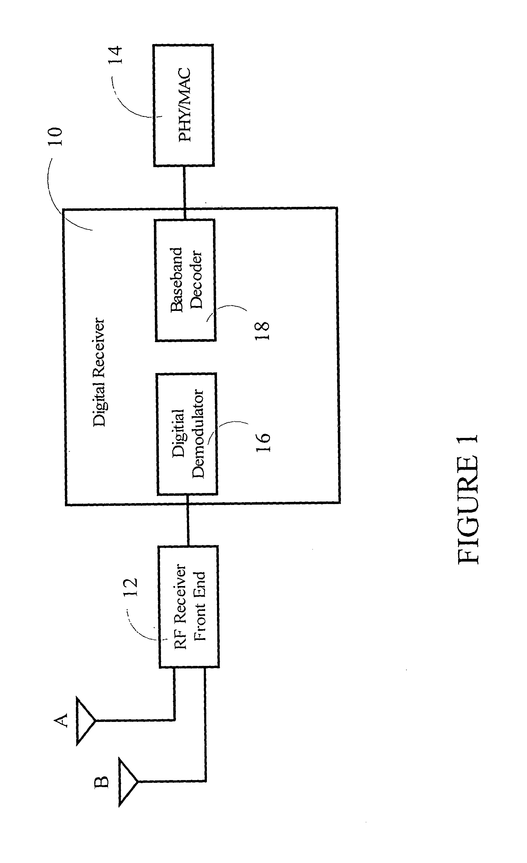
[0024] Referring to FIG. 1, there is depicted a digital receiver 10 in which the present invention is housed. The preferred receiver may be, for example, the ICE5350 Digital Receiver offered by IceFyre Semiconductor Inc. which performs all the physical layer functions detailed in the IEEE 802.11a standard, but the invention is not meant to be limited to this receiver. The digital receiver is located between the RF Receiver Front End 12 and the Physical Medium Access Control (PHY / MAC) 14. The RF Receiver Front End connects to antennae A and B. As shown in the drawing, the two main blocks within the digital receiver 10 are the digital demodulator 16 and the baseband decoder 18. The digital demodulator 16 recovers the baseband signal by removing carrier offsets, timing offsets, compensating for the channel impairments and demapping the digitally modulated signal. This block is located between the analog-to-digital interface (not shown) and the baseband interface (not shown). The baseba...


PUM


Abstract

The invention relates to the field of wireless communications, more particularly to a method of and device for automatic gain control (AGC) incorporating digitally controlled variable gain amplifiers (VGAs). The invention provides an AGC circuit comprising an I/Q baseband strip comprising multiple AGC stages wherein each of the AGC stages comprises: respective I and Q VGAs; a detector for detecting respective I and Q output signals received from the respective I and Q VGAs; an analogue to digital converter (ADC) for converting the detected I and Q output signals; and a digital engine for adjusting the respective I and Q VGAs for differences between the detected I and Q output signals and a reference signal. The use of staggered AGCs incorporating respective I and Q VGAs means that the total dynamic range is split between n-stages, thereby allowing for reduced gain requirements in the VGAs. Additionally, the use of digital control for setting the VGA gains means that analogue variations and I/Q gain imbalances are reduced. Additionally, the use of multiple update rates or magnitudes in the VGA control improves the dynamic settling time.

Description

CROSS-REFERENCE TO RELATED APPLICATIONS COPYRIGHT NOTICE [0001] A portion of the disclosure of this patent document contains material which is subject to copyright protection. The copyright owner has no objection to the facsimile reproduction by anyone of the patent document or the patent disclosure, as it appears in the Patent and Trademark Office patent file or records, but otherwise reserves all copyright rights whatsoever BACKGROUND OF THE INVENTION [0002] 1. Field of Invention [0003] The invention relates to the field of wireless communications, more particularly to a method of and device for digitally controlled variable gain amplification. [0004] 2. Description of the Related Prior Art [0005] Rapid growth in the portable communications market has pushed designers to seek low-cost, low-power, highly integrated solutions for the RF transceiver in accordance with the IEEE 802.11a-1999 Part 11: “Wireless LAN Medium Access Control (MAC) and Physical Layer (PHY) Specifications—High...

Claims


Application Information

Patent Timeline
Patent Type & Authority Applications(United States)
IPC IPC(8): H03G3/00H03G3/30H04L27/00
CPCH03G3/001H04L2027/0016H03G3/3052H03G3/00H03G3/20H03G3/30
Inventor BIRKETT, NEIL
Owner ZARBANA DIGITAL FUND
Why Eureka
Try Eureka