Sealing arrangement in a compressor

Inactive Publication Date: 2005-03-17
MES INT INC
View PDF12 Cites 32 Cited by
  • Summary
  • Abstract
  • Description
  • Claims
  • Application Information

AI Technical Summary

Benefits of technology

[0007] The present invention addresses the above needs and achieves other advantages, by providing a compressor sealing arrangement and method that utilize a supply of “

Problems solved by technology

Unfortunately, compressing the fuel in the engine's compressor also gives rise to a likelihood of fuel leaking into the surrounding environment.
However, in the case where the w

Method used


Image

  • Sealing arrangement in a compressor
  • Sealing arrangement in a compressor
  • Sealing arrangement in a compressor

Examples


first embodiment

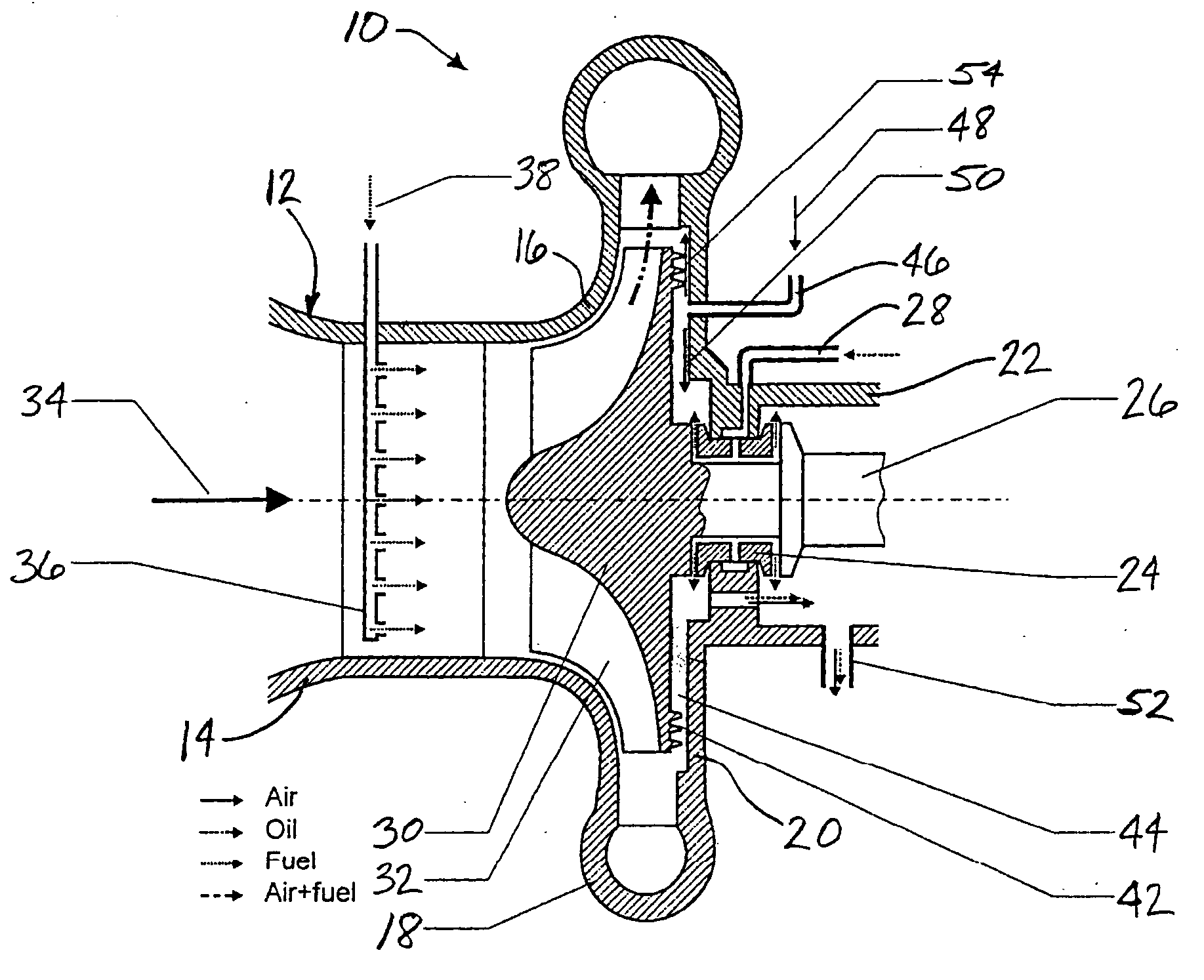
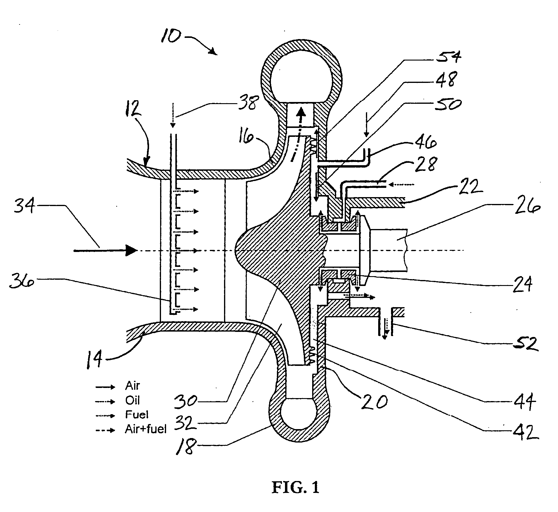
[0022]FIG. 1 depicts a compressor 10 in accordance with the invention. The compressor 10 includes a compressor housing 12 defining a generally tubular inlet duct 14 that extends generally axially. The housing 12 also defines an outer wall 16 that is joined to a downstream end of the inlet duct 14 and transitions from axially extending to generally radially extending; the outer wall 16 at its downstream end joins with a generally annular discharge duct 18 that surrounds the compressor. A rear end of the compressor housing includes a fixed wall 20 that extends radially inwardly from the discharge duct and lies opposite the wall 16. The radially inner end of the fixed wall 20 joins with a bearing casing 22 of the compressor.

[0023] The generally tubular bearing casing 22 houses at least one rotary bearing 24 for supporting a rotating shaft 26 that extends axially through the bearing casing. Lubricating oil is supplied to the bearing through at least one oil supply duct 28 that leads int...

second embodiment

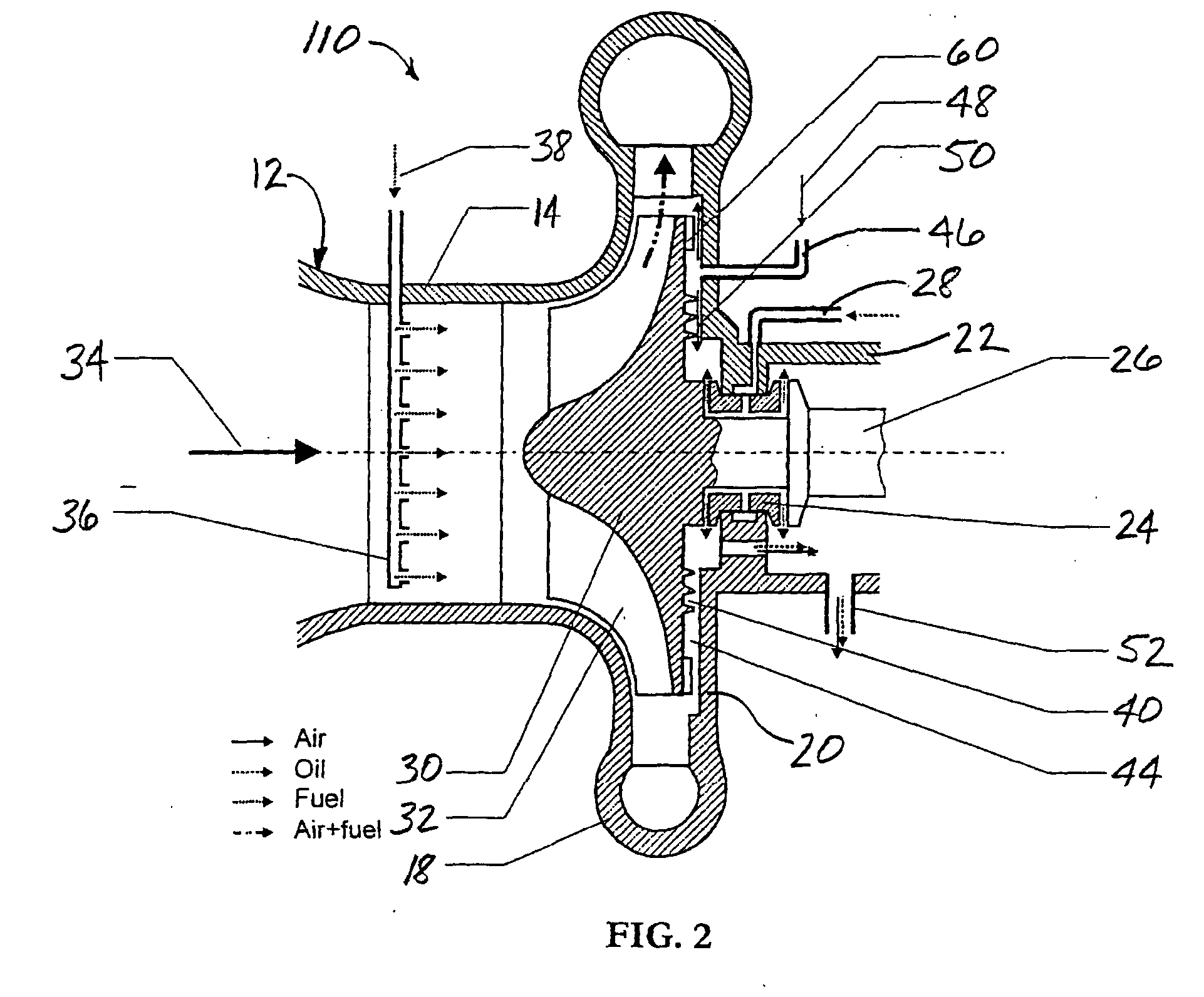
[0028] the invention is shown in FIG. 2. The compressor 110 of FIG. 2 is substantially similar to the compressor 10 of FIG. 1, except as noted below. The sealing arrangement of the compressor 110 includes a set of auxiliary blades 60 mounted on the rear surface of the compressor wheel 30, and may also include a hydraulic resistance element or seal 40 as shown. The auxiliary blades are spaced radially outward of the seal 40 such that a cavity or portion 44 of the leakage pathway is defined between the blades and the seal. A pressurized air supply duct 46 leads into the portion 44 of the leakage pathway. The auxiliary blades are configured to draw air radially outwardly through the blades and compress the air to a higher pressure. Accordingly, in this embodiment, the pressurized air 48 supplied through the supply duct 46 can be supplied at a pressure less than that in the main gas flow path of the compressor, but higher than the pressure in the bearing casing.

[0029] In operation, a po...

third embodiment

[0030] the invention is shown in FIG. 3. The compressor 210 of FIG. 3 is generally similar to the compressor 10 previously described, except as noted below. In this embodiment, the sealing arrangement of the compressor preferably employs three spaced seals. A first or inner seal 40 and a second seal 42 are arranged with a pathway portion or cavity 44 between them. A pressurized air supply duct 46 leads into this cavity 44 for supplying clean pressurized air 48 into the cavity. A third or outer seal 70 is spaced radially outwardly of the seal 42 such that a cavity 72 is defined between these seals. A recirculation duct 74 extends from the cavity 72 back to the compressor inlet duct 14. The first or inner seal 40 may be employed, but is not essential as previously noted.

[0031] In operation, clean pressurized air 48 is fed into the cavity 44 at a pressure higher than that in the bearing casing 22 but lower than that in the main gas flow path of the compressor. One portion 50 of the air...


PUM


Abstract

A sealing arrangement for a compressor that compresses a gaseous mixture of air and fuel includes a pressurized air supply duct for supplying pressurized air into a leakage pathway defined between a compressor wheel and a housing of the compressor, which leakage pathway leads from the main gas flow path into a bearing area of the compressor, the pressurized air being supplied at a pressure sufficient to ensure that air and gaseous fuel cannot flow from the main gas flow path through the leakage pathway into the bearing area. A portion of the pressurized air flows into the bearing area, while the remainder of the air flows outwardly and is either fed back into the main gas flow path or is combined with air and gaseous fuel that leaks past an outer seal and is recirculated back to the compressor inlet.

Description

FIELD OF THE INVENTION [0001] The invention relates to air compressors, and particularly to sealing arrangements for such compressors. BACKGROUND OF THE INVENTION [0002] Catalytic combustors are beginning to be used in recuperated microturbine power generation systems. A microturbine power generation system derives mechanical power for driving the electrical generator from a small gas turbine engine generally known as a microturbine. The engine generally includes at least one turbine that receives the hot combustion gases from a combustor and expands the hot gases to rotate the turbine. The turbine drives at least one compressor wheel that rotates within a compressor housing and supports blades that compress the working fluid passing through. In a recuperated gas turbine engine in which the combustor is a catalytic combustor, typically a gaseous mixture of air and fuel is supplied to the compressor as the working fluid, or separate air and fuel flows are fed to the compressor and th...

Claims


Application Information

Patent Timeline
IPC IPC(8): F01D3/04F01D11/02F01D11/04F02C7/28F04D29/12F04D29/16F04D29/58
CPCF01D3/04F01D11/02F01D11/04F04D29/5846F04D29/124F04D29/162F02C7/28F04D29/08F04D29/16
Inventor BELOKON, ALEXANDEROSOBOV, VICTORTOUCHTON, GEORGE L.OSOBOVA, VALENTINA
Owner MES INT INC
Why Eureka
Try Eureka