
Attachment system for bicycle accessories

a technology for attaching systems and bicycle accessories, which is applied in the directions of bicycle equipment, biocide, plant/algae/fungi/lichens ingredients, etc., can solve the problems of inability to “quick release”, inconvenient or inconvenient mounting of various accessories, and difficulty in simultaneous mounting of other accessories, etc., to achieve the effect of increasing the flexibility of the attaching system

Inactive Publication Date: 2005-03-17
TRANSBIKE SYST
View PDF55 Cites 5 Cited by
  • Summary
  • Abstract
  • Description
  • Claims
  • Application Information

AI Technical Summary

Benefits of technology

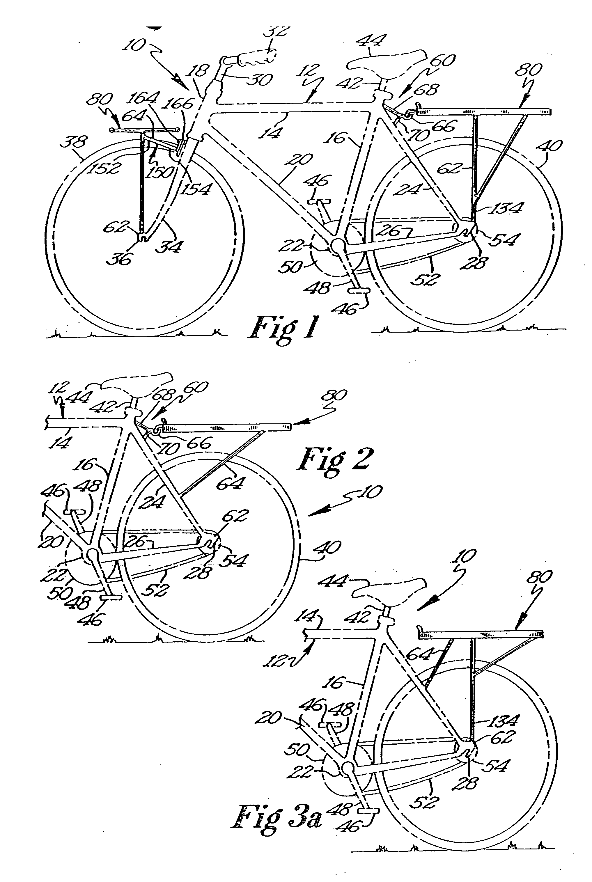
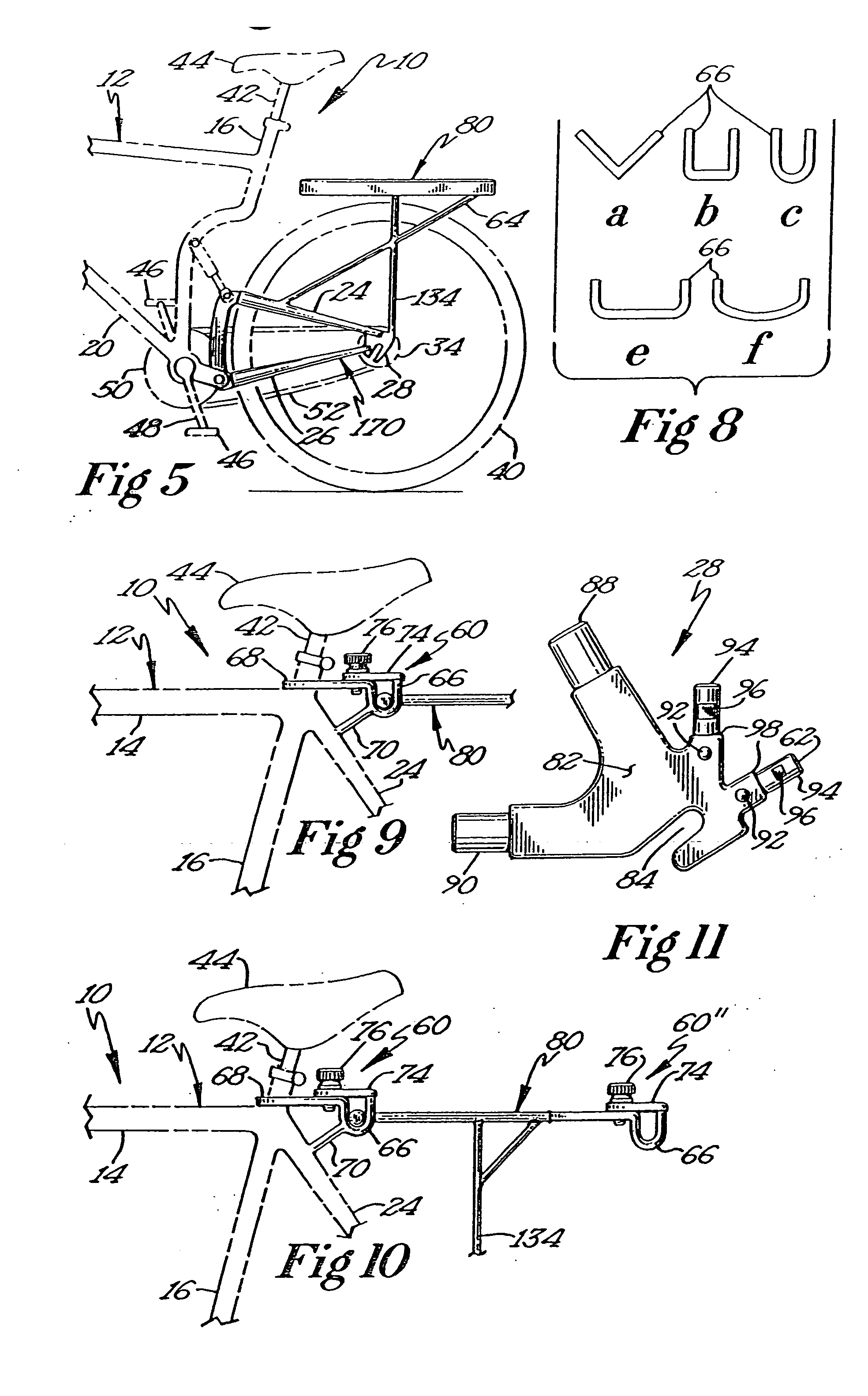
[0014] Because the size and configuration of accessories that may be used with a bicycle will vary greatly, the position and orientation of the upper mount and the mounting posts may be varied as well. Specifically, the upper mount is preferably positioned at a location that is adjacent to the intersection of the seat stay and the seat tube of the bicycle frame. However, while remaining adjacent to the aforementioned junction, the channel of the upper mount may in fact be slightly above the intersection of the seat stay and seat tube, substantially level with the intersection of the seat stay and seat tube, or below the level of the intersection of the seat stay and seat tube. In addition, the upper mount may be formed integrally with the frame of the bicycle or may be retrofit thereto. Typically, the upper mount comprises a channel that is supported on a cantilever arm that is itself secured to the frame of the bicycle as described hereinabove. This cantilever arm may also be aided by an angled support that extends between the frame of the bicycle and the channel or the distal end of the cantilever arm to add further strength to the upper mount.
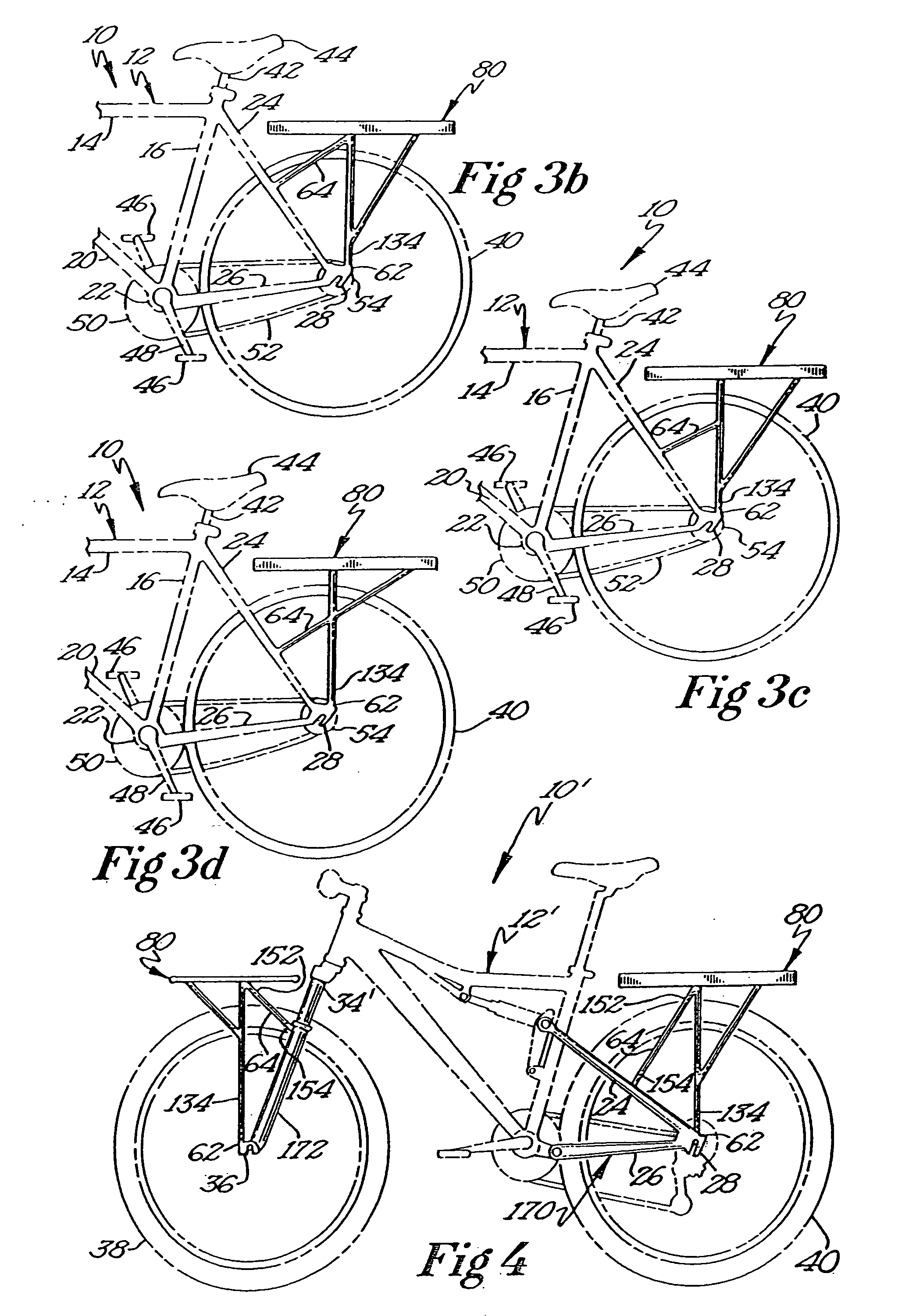
[0019] Yet another embodiment of the present invention comprises the use of a mounting post and a rigid support to secure an accessory to the bicycle frame. This embodiment of the attachment system of the present invention is particularly useful for securing accessories to front and rear suspensions of a fully suspended bicycle frame, as the attachment of the accessory solely to the suspension members themselves allows the accessories to be maintained in the same frames of reference as the respective suspension mechanisms.
[0020] It is to be understood that the accessory mounting posts of the present invention may be formed integral with the front or rear dropout of a bicycle frame or may be retrofit thereto. One embodiment of the mounting posts that may be retrofit to a dropout includes a relatively planar mounting plate from which extends one or more mounting posts. The mounting plate includes one or more holes formed therethrough that are substantially aligned with preexisting holes formed through the dropout of the bicycle frame. The mounting plate, and subsequently the mounting posts, is attached to the dropout by use of a threaded fastener, a metallic weld, or an adhesive. The mounting posts themselves can be said to comprise an improvement over typical prior art bicycle dropouts. These accessory mount posts represent hard point connections directly to the frame of a bicycle. Accessory mounting legs that are constructed and arranged to mate with the accessory mounting posts are an essential part of the attachment system of the present invention. Providing multiple mounting posts on a dropout of a bicycle provides the opportunity to secure multiple accessory mounting legs to the bicycle frame at the dropout, again increasing the flexibility of the attachment system of the present invention.

Problems solved by technology

At times, the mounting system of one available accessory makes simultaneous mounting of other accessories difficult, inconvenient, or impossible.
Generally, the various accessory mounts are incompatible.
While these means for attaching accessories to a bicycle do have utility, they are not “quick-release”.
Furthermore, other than the braze-on, these attachment means are not part of the bicycle frame itself and rely on a clamping-type mechanical grip that may fail, thereby releasing the accessory or damaging the bicycle frame or its finish.
Braze-ons are themselves relatively limited in their location and number.
These attachment means are also not very adaptable.
Where a member of a bicycle frame is not in an assumed orientation or where the frame member is of a different size or shape, the aforementioned prior art accessory attachment means may not easily be modified to accommodate common variations in bicycle frame size and shape.
Many bicycles currently on the market also incorporate front and / or rear suspension systems that can make it difficult to attach accessories to a bicycle.
This creates serious problems in the attachment of accessories to a bicycle frame, as the traditional points of attachment may be in different frames of reference vis-à-vis the frame and the suspension.
Finally, typical prior art accessory attachment means are not generally able to withstand rigorous loading conditions.
Heavy loads, such as those seen in long distance touring bicycles and in work bicycles, may easily exceed the holding abilities of most, if not all, of the aforementioned accessory attachment means.

Method used


Image

  • Attachment system for bicycle accessories
  • Attachment system for bicycle accessories
  • Attachment system for bicycle accessories

Examples


Embodiment Construction

[0055] Although the disclosure hereof is detailed and exact to enable those skilled in the art to practice the invention, the physical embodiments herein disclosed merely exemplify the invention, which may be embodied in other specific structure. While the preferred embodiment has been described, the details may be changed without departing from the invention, which is defined by the claims.

[0056]FIG. 1 illustrates a standard bicycle 10 that incorporates the attachment system of the present invention. The bicycle 10 comprises a frame 12 of standard configuration that is made up of a plurality of frame members. While the shape, size, and orientation of the respective frame members may vary with the make of the bicycle, a standard bicycle frame 12 is composed of a top-tube 14 that is coupled between a seat tube 16 and a head tube 18. The seat tube 16 receives telescopically therein a seat post 42 that supports the seat 44. A down tube 20 extends between the lower end of the head tube...


PUM


Abstract

A system for attaching bicycle accessories to the frame of a bicycle is disclosed. The system includes a channel mount secured to the frame of the bicycle adjacent the junction of the seat post and seat stay of a bicycle frame. The channel mount forms a hard point attachment for a portion of the bicycle accessory. Alternatively, a mounting mechanism is provided that is operatively configured to be secured to a bicycle dropout frame member. The mounting mechanism includes a post extending away from the bicycle dropout that is shorter than an outer radius of a wheel mounted in the bicycle dropout frame member. In addition, a system for attaching an accessory to a front fork of a bicycle frame is provided. The system includes a lower mount secured to a front bicycle dropout and a rigid support secured proximate to the front fork.

Description

CROSS REFERENCE TO RELATED APPLICATIONS [0001] This application claims the benefit of Provisional Application Ser. No. 60 / 342,917 filed Dec. 20, 2001 and Provisional Application Ser. No. 60 / 369,491 filed Apr. 1, 2002, and priority to International PCT Application Serial No. PCT / US02 / 040922, filed Dec. 20, 2002.FIELD OF THE INVENTION [0002] The present invention relates generally to apparatus for mounting one or more accessories to a bicycle. More particularly, this invention pertains to a system for interchangeably mounting a variety of accessories, either alone or in simultaneous combination, to a bicycle frame. BACKGROUND OF THE INVENTION [0003] There are many accessories that are currently useful to bicyclists. These include removable fenders over the front and / or rear wheels, bicycle cargo carrying racks that may be positioned over either wheel, cargo-carrying racks with integral baskets, saddlebags or panniers-that are generally mounted on a cargo-carrying rack and even small t...

Claims


Application Information

Patent Timeline
Patent Type & Authority Applications(United States)
IPC IPC(8): B62J7/02B62J7/04B62J7/06B62J99/00B62K19/40
CPCB62J7/02B62K19/40B62J7/06B62J7/04
Inventor OCKENDEN, LYNN MARIE
Owner TRANSBIKE SYST
Learn More