Control system for a hydro-mechanical transmission

a control system and hydro-mechanical technology, applied in the direction of fluid couplings, gearings, couplings, etc., can solve the problems of increasing the size of the planetary gear train, poor efficiency, disadvantage in economical efficiency, etc., to reduce the capacity of the effect of reducing the load and heat load imposed on the forward and reverse clutches

Inactive Publication Date: 2005-03-17
KOMATSU LTD
View PDF8 Cites 37 Cited by
  • Summary
  • Abstract
  • Description
  • Claims
  • Application Information

AI Technical Summary

Benefits of technology

[0025] According to the invention, when the rotational speed of the output shaft is increased, the first pump / motor is coupled to the input shaft by the coupling / decoupling clutch mechanism so that the transmission serves as an output-split type HMT. On the other hand, when the rotational speed of the output shaft is decreased, the first pump / motor is coupled to the output shaft by the coupling / decoupling clutch mechanism so that the transmission serves as an input-split type HMT. As a result, hydraulic power can be allowed to constantly flow in a forward direction. In such a transmission which selectively functions as an output-split type HMT or as an input-split type HMT, when initiating operation for shifting the transmission of the vehicle from forward to reverse or vice versa, a relief set pressure of the variable relief valve inserted in the hydraulic piping for connecting the first pump / motor to the second pump / motor is reduced in response to switching of the forward / reverse (F / R) shifting clutch mechanism, and after completion of the switching of the F / R shifting clutch mechanism, the relief set pressure is increased. Thus, pressure oil within the hydraulic piping for connecting the first pump / motor to the second pump / motor is drained when the F / R shifting clutch mechanism is switched, so that it becomes unnecessary to carry out gear shifting by sliding engagement of the forward or reverse clutch of the F / R shifting clutch mechanism and gear shifting can be carried out by hydraulic control of the hydraulic piping alone. In consequence, the load and heat load imposed on the forward and reverse clutches can be reduced and therefore the capacity of the forward and reverse clutches can be reduced.

Problems solved by technology

As just described, when hydraulic power flows in the reverse direction, a large flow of energy occurs in each element, resulting in poor efficiency.
7(a) and 7(b), if part of energy flows in the reverse direction, the energy that pass through the mechanical unit will increase, and therefore, there arises a need to increase the size of the planetary gear train, which leads to a disadvantage in economical efficiency.
However, such sliding engagement of the forward or reverse clutch during operation for shifting the transmission of the vehicle between forward and reverse causes higher load and heat load on the forward and reverse clutches, with higher vehicle speed before initiating the gear shifting operation.

Method used


Image

  • Control system for a hydro-mechanical transmission
  • Control system for a hydro-mechanical transmission
  • Control system for a hydro-mechanical transmission

Examples


Embodiment Construction

[0033] Referring now to the accompanying drawings, a control system for a hydro-mechanical transmission will be concretely described according to one preferred embodiment of the invention.

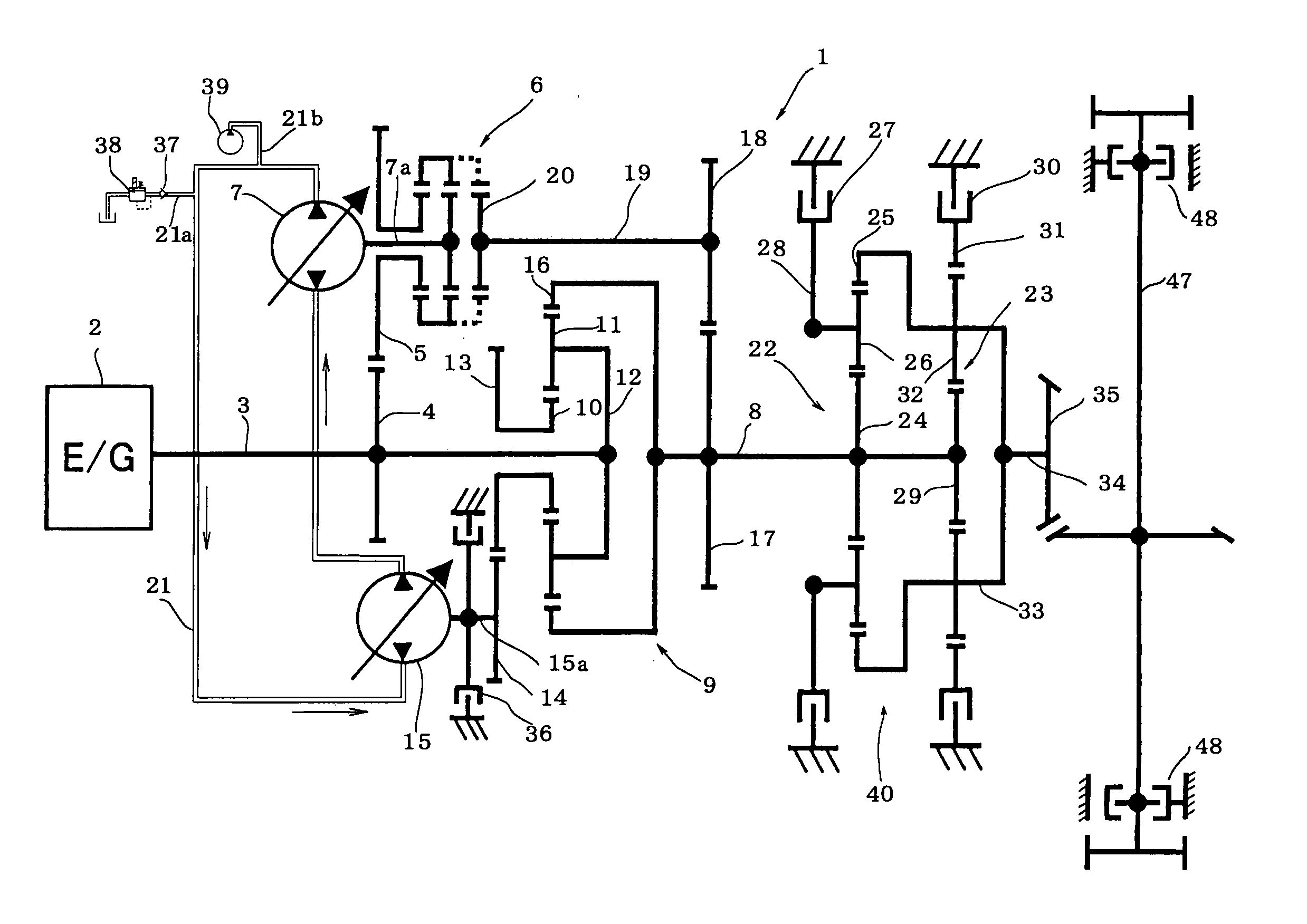
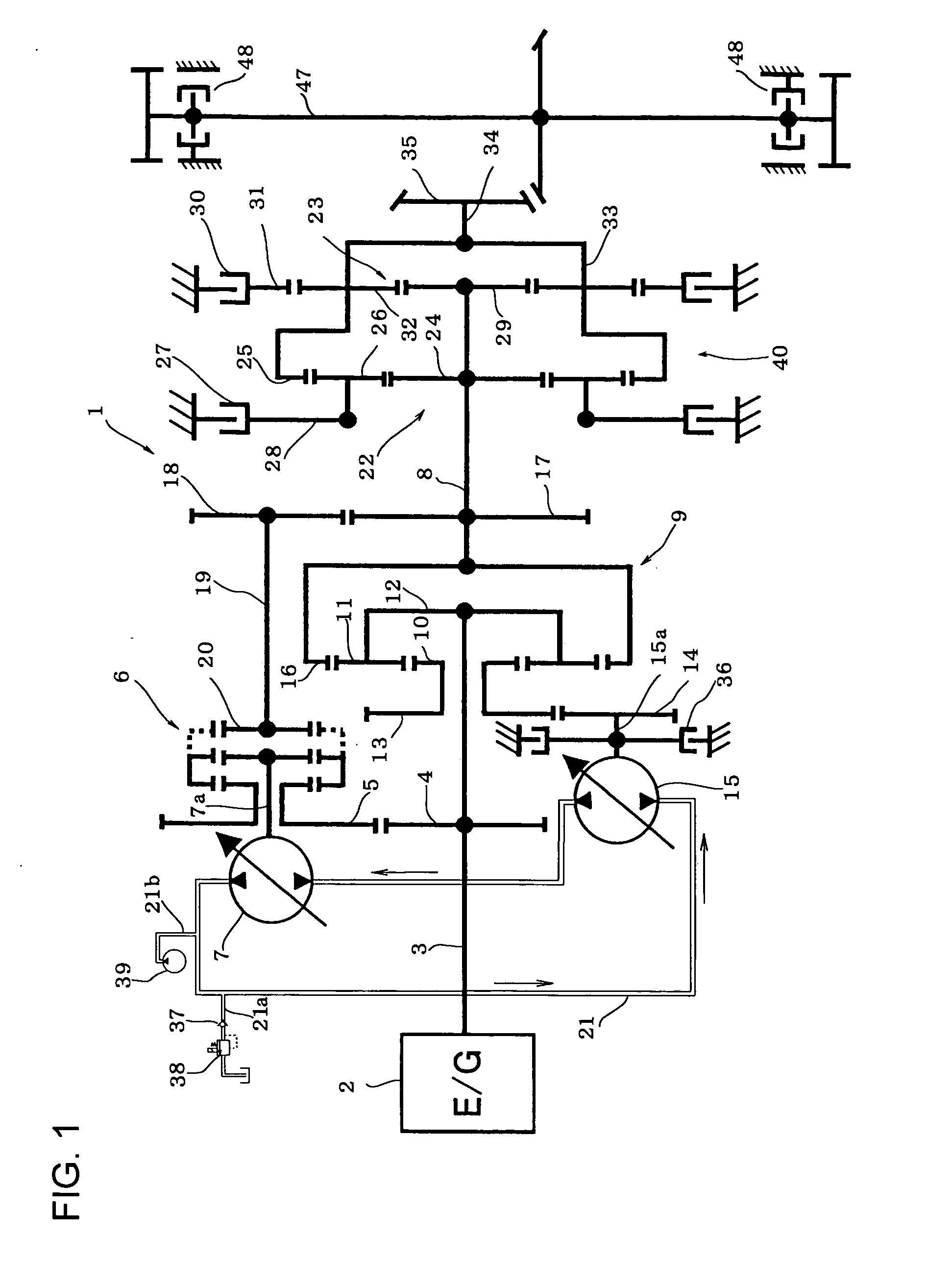
[0034]FIG. 1 is a schematic structural diagram of a control system for a hydro-mechanical transmission constructed according to an embodiment of the invention. While the invention is applied to a transmission for a track-type vehicle such as bulldozers in this embodiment, it is obvious that the invention is not limited to this application.

[0035] In a hydro-mechanical transmission 1 constructed according to this embodiment, a first gear 4 is secured to an input shaft 3 to which power from an engine 2 is input. A second gear 5 meshes with the first gear 4 such that it can be coupled to a shaft 7a of a first pump / motor 7 through an coupling / decoupling clutch mechanism (hereinafter referred to as “clutch mechanism”) 6 such as a synchromesh mechanism. The clutch mechanism 6 is situated between the sec...


PUM


Abstract

A variable relief valve is inserted in a hydraulic piping for connecting a first pump / motor to a second pump / motor. The variable relief valve is controlled such that when shifting the transmission from forward to reverse or vice versa, a relief set pressure of the variable relief valve is reduced in response to switching of a forward / reverse shifting clutch mechanism and after completion of the switching of the forward / reverse shifting clutch mechanism, the relief set value is increased.

Description

TECHNICAL FIELD [0001] The present invention relates to a control system for a hydro-mechanical transmission designed to transmit power from the input shaft to the output shaft through a mechanical transmission unit and a hydrostatic transmission unit. BACKGROUND ART [0002] There have been known hydro-mechanical (power split type) transmissions (HMTs) which hydraulically transmit part of input power while mechanically transmitting the remaining part of it. Since mechanical power is transmitted with high efficiency, hydro-mechanical transmissions (HMTs) are designed to convert only part of mechanical power into hydraulic power, so that they can achieve high transmission efficiency. By virtue of this, they are considered to be ideal transmissions for vehicles subjected to wide load variations such as bulldozers and wheel loaders and some of them are, in fact, employed in such vehicles. [0003] In a typical hydro-mechanical transmission (HMT), variable speed characteristics are achieved...

Claims


Application Information

Patent Timeline
Patent Type & Authority Applications(United States)
IPC IPC(8): F16H47/04F16H61/40F16H61/42F16H61/66
CPCF16H47/04F16H61/40F16H61/4017F16H2037/044B60W30/18045F16H2037/0866F16H2037/088F16H2200/2064B60W10/18F16H2037/049
Inventor FUNATO, MASAHIROOKADA, TOSHIKAZUYAMAMOTO, SHIGERUNAKAGAWA, TOMOHIRO
Owner KOMATSU LTD
Why Eureka
Try Eureka