Eureka AIR delivers breakthrough ideas for toughest innovation challenges, trusted by R&D personnel around the world.

Expanded metal

Active Publication Date: 2005-03-24
BREMBANA & ROLLE
View PDF23 Cites 6 Cited by
  • Summary
  • Abstract
  • Description
  • Claims
  • Application Information

AI Technical Summary

Benefits of technology

[0029] When expansion force is applied to slit metal or intermediate product, the longitudinal expansion is accompanied by a transverse contraction. This effect is most pronounced at high stretching angles, and in particular at stretching angles above about 85 degrees. According to the invention the force transmitters are arranged so that they can move towards each other in the second direction while applying extension force. In this way the expansion force can continue to be evenly distributed to the expanded metal in the course of the expansion. In this way it is prevented that e.g. the expansion is larger at the circumference of the sheet as compared to the central region. Therefore it is achieved that deviations from the repetition length over the sheet are minimized and a relatively uniform shape of openings is obtained, also and in particular for overstretched expanded metal.

Problems solved by technology

However, applicant has found that the deviations from perfect rhombical or frustro-rhombical shape make it difficult to use expanded metal in a staggered arrangement like in U.S. Pat. No. 4,143,709, since at least two different types of passageways are formed with slightly different cross-section and shape, which is undesirable for optimum tube support.

Method used


Image

  • Expanded metal
  • Expanded metal
  • Expanded metal

Examples


Embodiment Construction

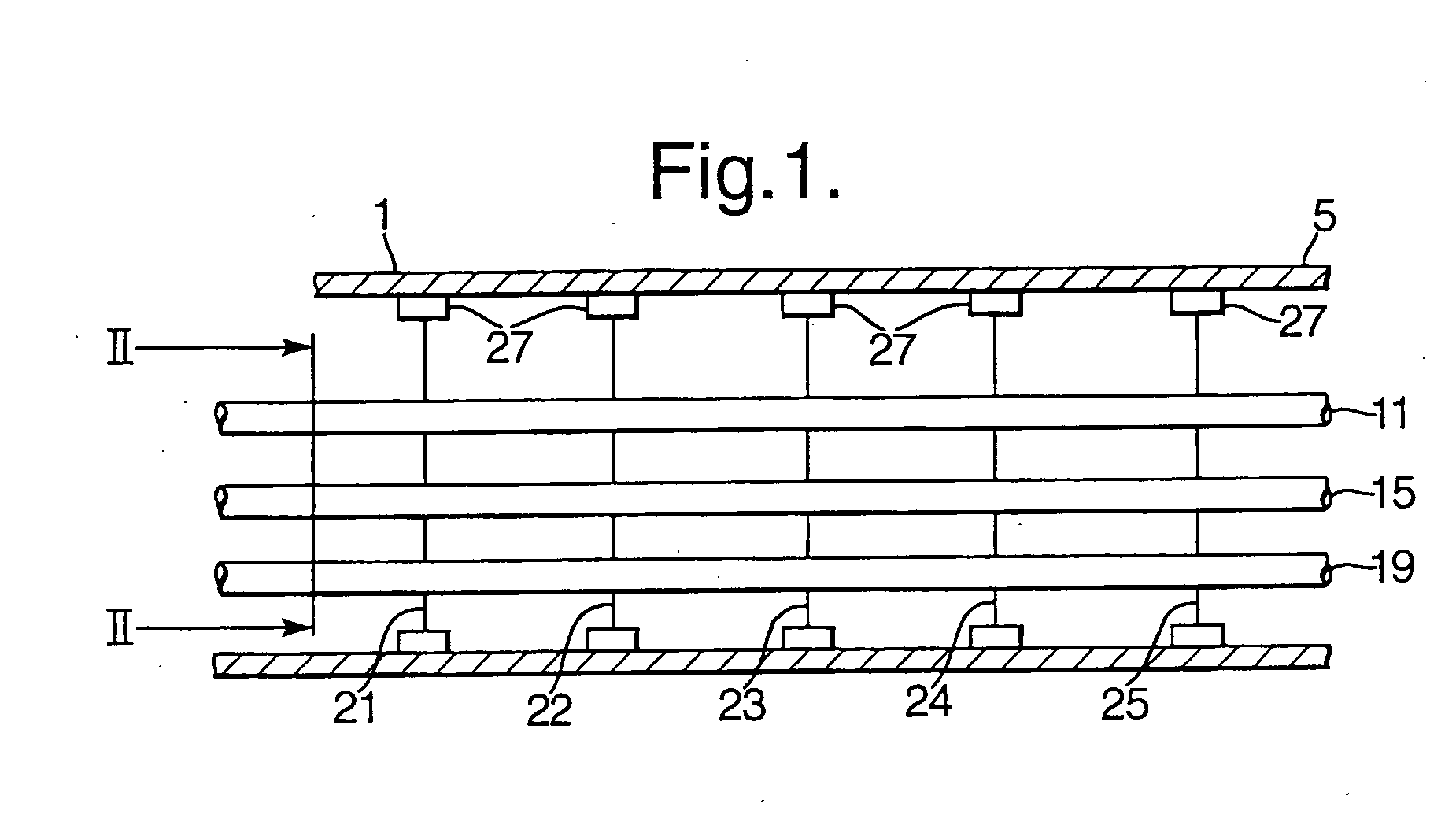
[0046] Reference is made to FIG. 1 showing part of a longitudinal section through a heat exchanger 1 in the form of a cylindrical vessel having a cylindrical shell 5. A tube bundle formed of a plurality of parallel tubes, of which tubes 11, 15, and 19 are shown, is installed in the heat exchanger. The length direction of the tubes is parallel to the axis of the cylindrical shell 5. The support for the tube bundle is formed by axially spaced apart transverse support plates 21, 22, 23, 24 and 25 supporting the intermediate parts of the tubes in the cylindrical shell 5 (not shown). Please note that FIG. 1 does not show the end parts of the tubes with the tube sheet.

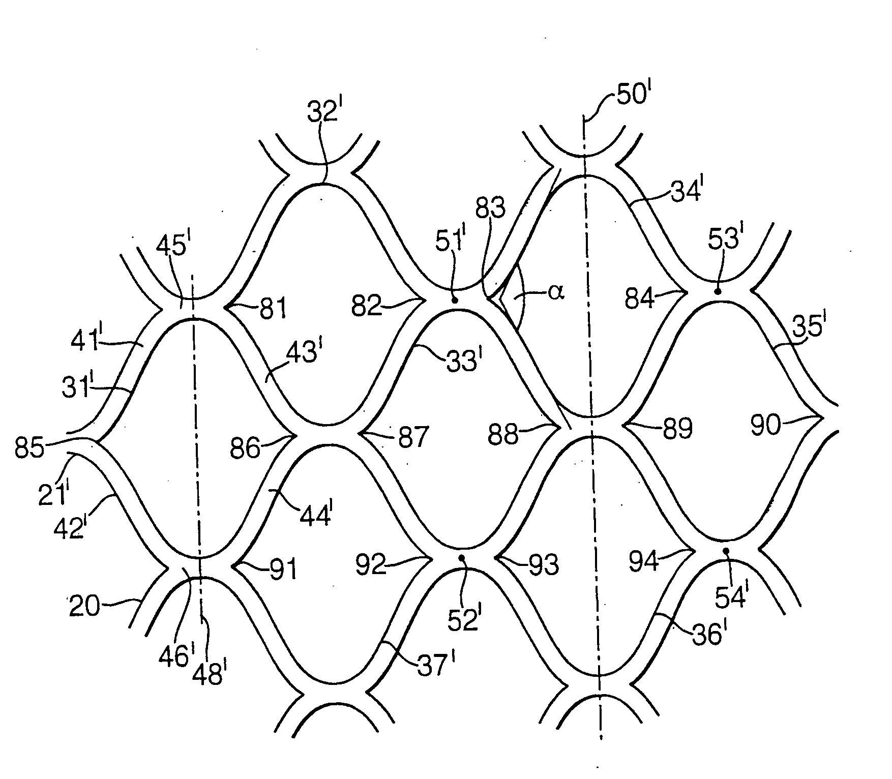
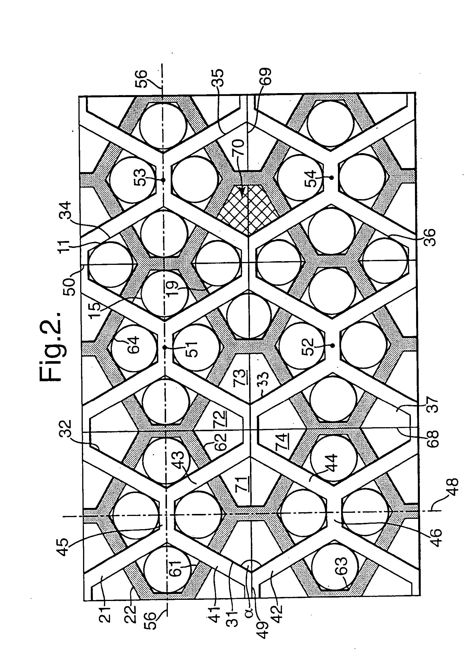
[0047] Reference is made to FIG. 2 showing schematically a suitable geometry of the arrangement of openings in support plates, as a view of the central part of support plates 21 and 22 along the longitudinal axis of the cylindrical shell 5 in FIG. 1. For the sake of clarity, FIG. 2 is drawn at a larger scale than FIG. 1, th...


PUM

PropertyMeasurementUnit
Angleaaaaaaaaaa
Angleaaaaaaaaaa
Angleaaaaaaaaaa

Abstract

A sheet of expanded metal produced by slitting a sheet of metal, and stretching along a stretching direction, which sheet of expanded metal forms a grid of openings having a first repetition length in the stretching direction and a second repetition length in the direction perpendicular to the stretching direction, wherein the first and second repetition lengths are substantially equal. A sheet of expanded metal having a stretching angle larger than 90 degrees. Use of a sheet of expanded metal according to the invention for supporting a bundle of parallel tubes. A method of manufacturing expanded metal from pre-expanded metal, wherein expansion force is applied at a plurality of points perpendicular to the stretching direction, wherein the expansion force is applied using a plurality of force transmitters co-operating with the plurality of points, and wherein the force transmitters are arranged so that they can move towards each other in the second direction while applying extension force.

Description

FIELD OF THE INVENTION [0001] The present invention relates to a sheet of expanded metal, to a method of producing a sheet of expanded metal, and to the use of such expanded metal as support for a bundle of parallel tubes. BACKGROUND OF THE INVENTION [0002] A sheet of expanded metal is conventionally made from sheet metal that is slit according to an arrangement of staggered parallel dashed lines, and stretched (expanded) perpendicular to the dashed lines into a structure of cross laths with interstices. Its manufacture is generally cheap. Moreover the sheets can easily be cut to a desired shape for a particular application, e.g. circular, for example by laser cutting. [0003] The sheet of expanded metal forms a regular grid of openings, wherein each opening is defined by two substantially V-shaped pairs of strands, wherein the strands of each pair are adjoined in the direction of stretching and define a stretching angle, and two bonds interconnecting the two pairs of strands at the ...

Claims


Application Information

Patent Timeline
IPC IPC(8): F16L3/26F28F9/013
CPCF16L3/26F28F9/0131Y10T29/49373Y10T29/18Y10T29/4935F28F2255/12F28F9/00F28F9/007F28F9/013F16L3/00
Inventor MULDER, DOMINICUS FREDERICUS
Owner BREMBANA & ROLLE
Why Eureka
Eureka Blog
Learn More