Vehicular brake system component
a brake system and component technology, applied in the direction of brake systems, brake components, brake cylinders, etc., can solve the problems of spoiling sealing performance, excessive expansion or contraction of the diaphragm, etc., and achieve satisfactory peeling strength, satisfactory sealing performance, and enhanced peeling strength between the metal member and the adhesive layer
- Summary
- Abstract
- Description
- Claims
- Application Information
AI Technical Summary
Benefits of technology
Problems solved by technology
Method used
Image
Examples
first embodiment
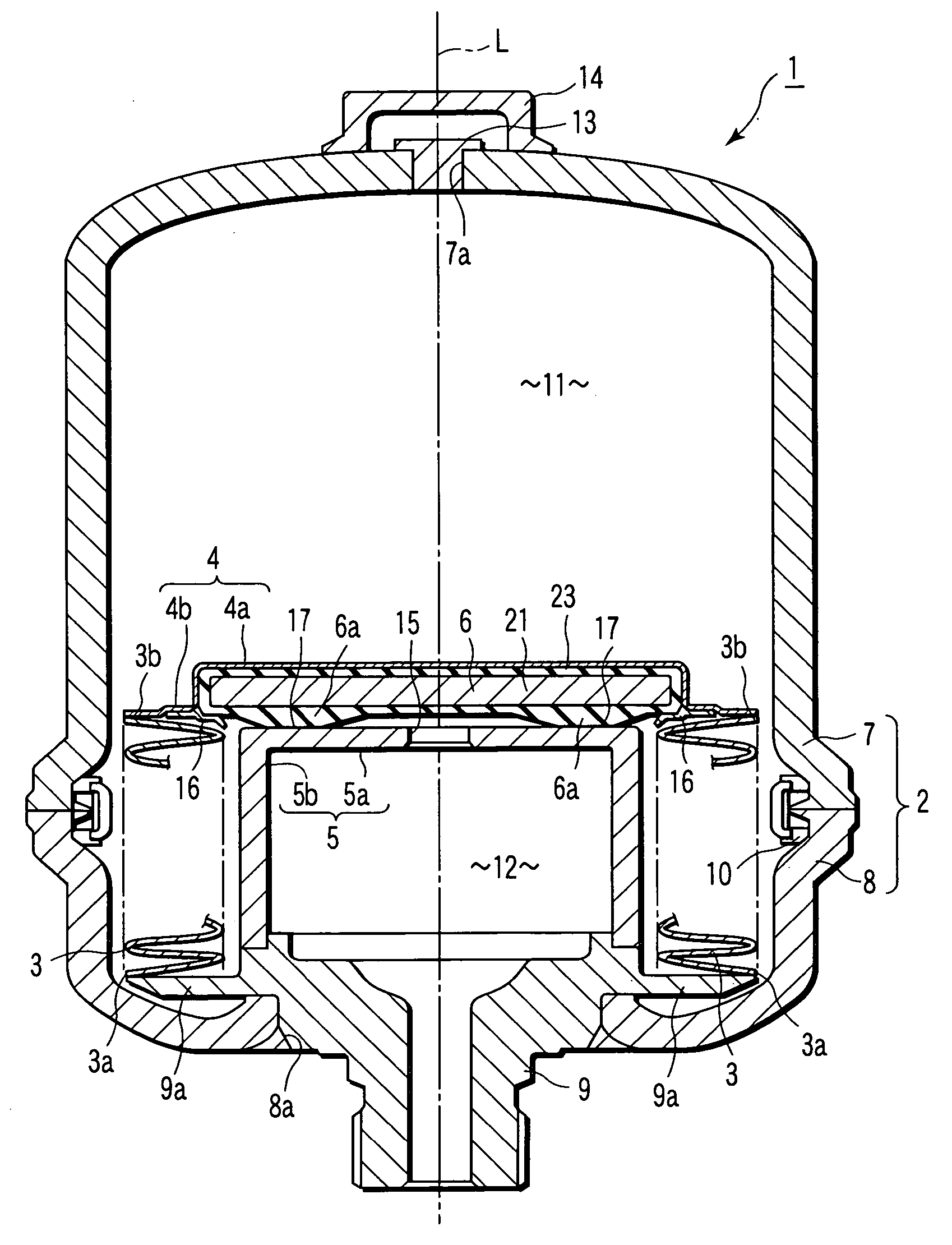
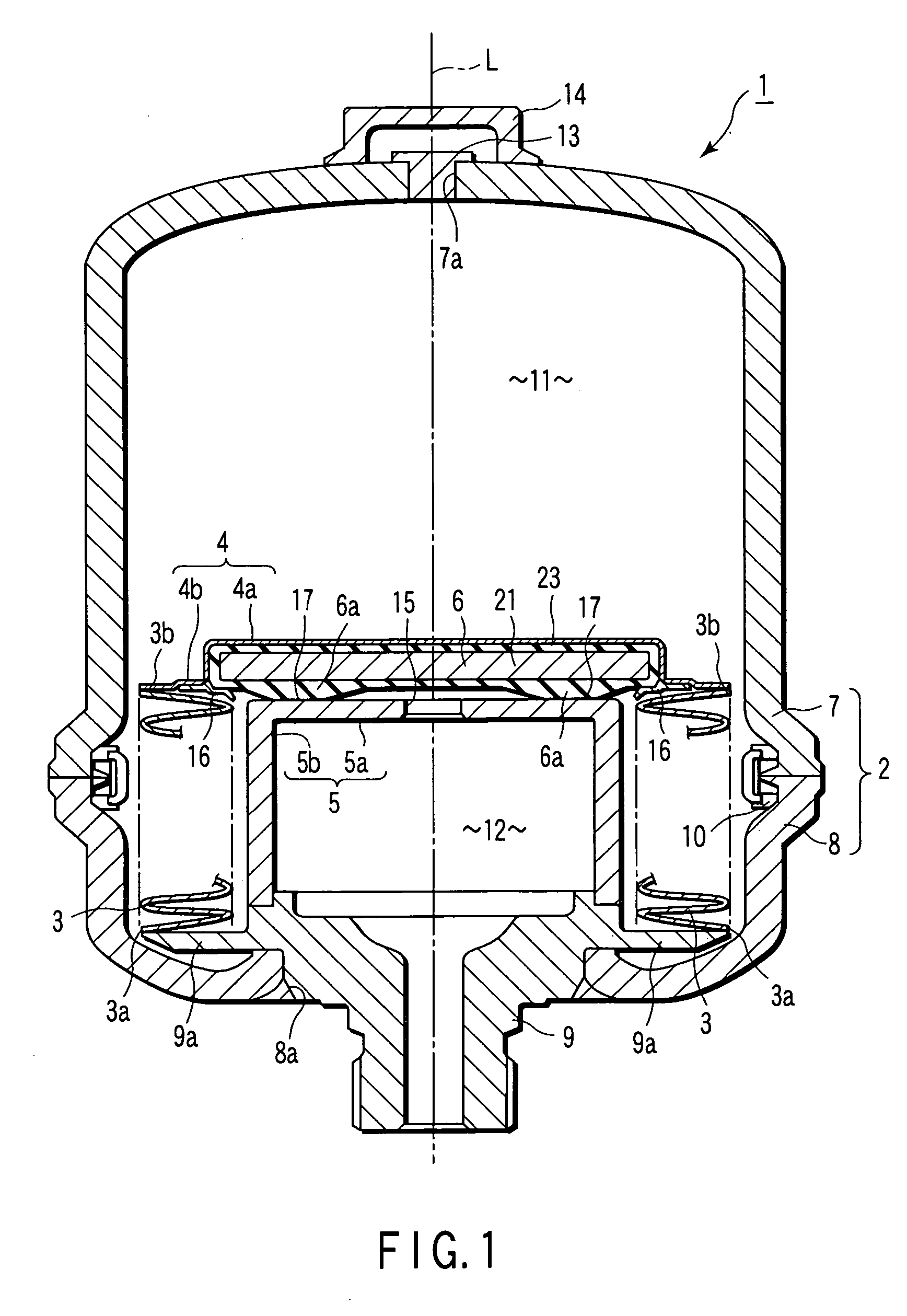
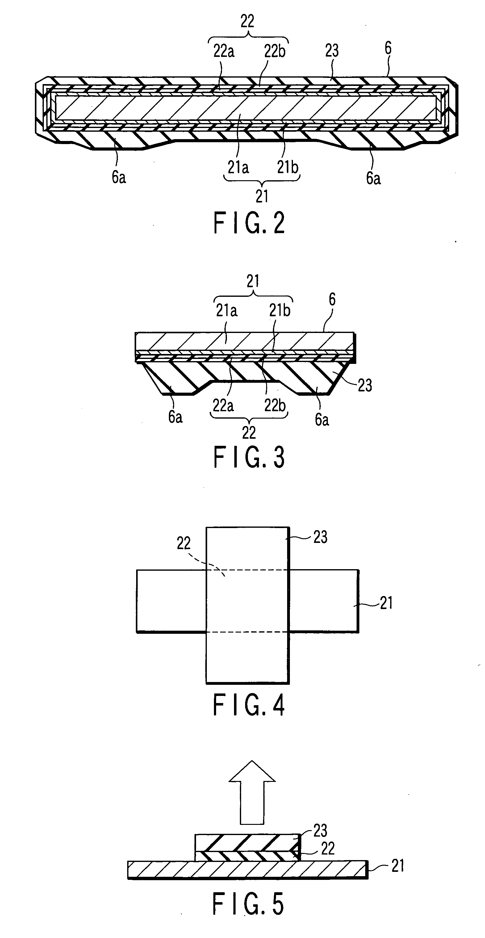
[0039] the present invention will now be described with reference to FIGS. 1 and 2. In connection with the present embodiment, an accumulator will be explained as a vehicular brake system component.
[0040] As shown in FIG. 1, an accumulator 1 as a vehicular brake system component comprises a pressure vessel 2, metallic bellows 3 as a diaphragm, cap portion 4, partition wall 5, seal member 6, etc. The seal member 6 serves also as a sealable bonded component.
[0041] The accumulator 1 is used to store pressure generated in a hydraulic-pressure device and absorb hydraulic pulsation. In the description of the present embodiment to follow, the accumulator 1 is supposed to be used as the hydraulic-pressure device in a hydraulic brake device as a vehicular brake system that is attached to a vehicle such as an automobile.
[0042] The pressure vessel 2 has first and second shells 7 and 8. Each of the first and second shells 7 and 8 is a bottomed cylinder that is formed by forging or the like. T...
second embodiment
[0122] the present invention will now be described with reference to FIGS. 8 to 10. In connection with the present embodiment, a master cylinder will be described as an example of the vehicular brake system component. A master cylinder 31 of the present embodiment is constructed in the same manner as an existing master cylinder except for the structure of a center valve 34.
[0123] As shown in FIG. 8, the master cylinder 31 is a device that converts an operating force applied to an input mechanism through a brake pedal or the like into a liquid pressure. It comprises a body 32, a rod 33, the center valve 34 for use as a liquid pressure generating mechanism, a piston 35, etc. In the body 32, the rod 33, valve 34, and piston 35 are arranged in the order named. The rod 33 has an abutting portion 33a on the side of the valve 34. The valve 34 is a sealable bonded component that serves also as a seal member. The center valve 34 has a metal member 21, adhesive layer 22, and elastic rubber me...
third embodiment
[0127] the present invention will now be described with reference to FIGS. 11 to 12. In connection with the present embodiment, a plunger pump will be described as an example of the vehicular brake system component. A plunger pump 41 of the present embodiment is constructed in the same manner as an existing plunger pump except for the structure of a seal member 44.
[0128] As shown in FIG. 11, the plunger pump 41 comprises a body 42, a shaft 43, the seal member 44, etc. The shaft 43 is located in the body 42. Further, a pump suction chamber 45 is defined in the body 42. In the plunger pump 41 that is used as the brake system component, the suction chamber 45 doubles as a cam chamber. The ring-shaped seal member 44 cuts off a brake fluid from the suction chamber 45. The seal member 44 is located along the outer periphery of the shaft 43. The seal member 44 is also a sealable bonded component. It has a metal member 21, adhesive layer 22, and elastic rubber member 23, and is constructed ...
PUM
 Abstract
Description
Claims
Application Information
 - R&D
- Intellectual Property
- Life Sciences
- Materials
- Tech Scout
- Unparalleled Data Quality
- Higher Quality Content
- 60% Fewer Hallucinations
Browse by: Latest US Patents, China's latest patents, Technical Efficacy Thesaurus, Application Domain, Technology Topic, Popular Technical Reports.
© 2025 PatSnap. All rights reserved.Legal|Privacy policy|Modern Slavery Act Transparency Statement|Sitemap|About US| Contact US: help@patsnap.com


