Organic laser and liquid crystal display

a laser and liquid crystal display technology, applied in semiconductor lasers, non-linear optics, instruments, etc., can solve the problems of reducing power efficiency, reducing display contrast, and reducing power efficiency, so as to improve the overall efficiency of the liquid crystal display and simplify the integrated structure.

Inactive Publication Date: 2005-03-24
EASTMAN KODAK CO
View PDF21 Cites 74 Cited by
  • Summary
  • Abstract
  • Description
  • Claims
  • Application Information

AI Technical Summary

Benefits of technology

[0009] The present invention has the advantage that a simple integrated structure can be employed to create a white lig

Problems solved by technology

This conventional design for creating a display suffers from the need to use a polarizing film to create polarized light.
Approximately one half of the light is lost from the backlight; thus, reducing power efficiency.
Just as significantly, imperfect polarization provided by the polarizing film reduces the contrast of the display.
Moreover, the required additional use of a co

Method used


Image

  • Organic laser and liquid crystal display
  • Organic laser and liquid crystal display
  • Organic laser and liquid crystal display

Examples


Embodiment Construction

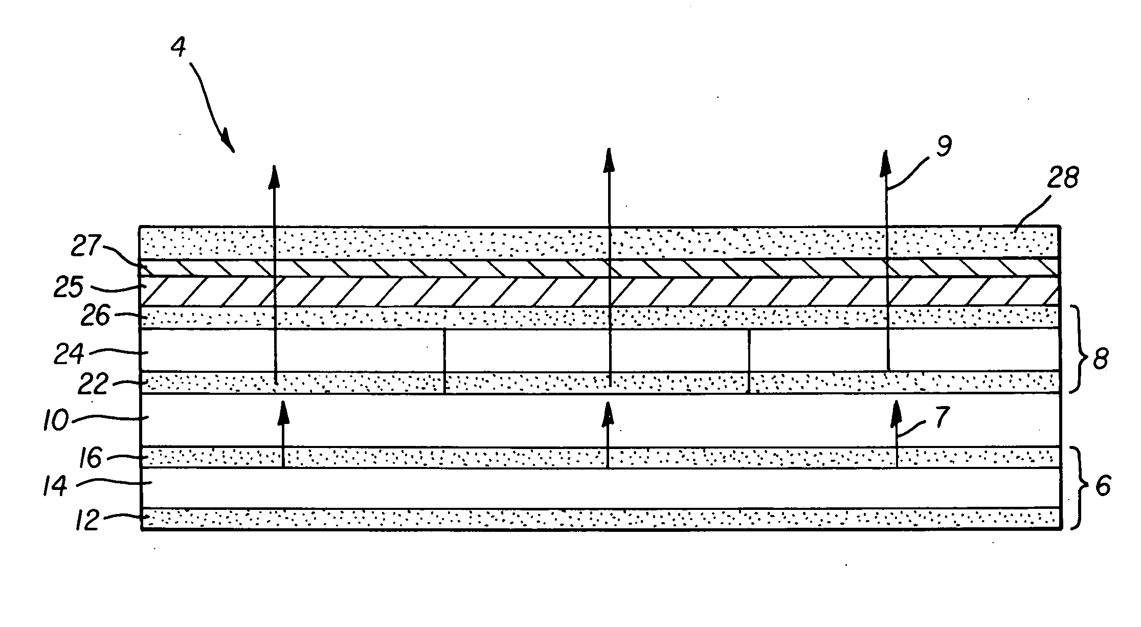
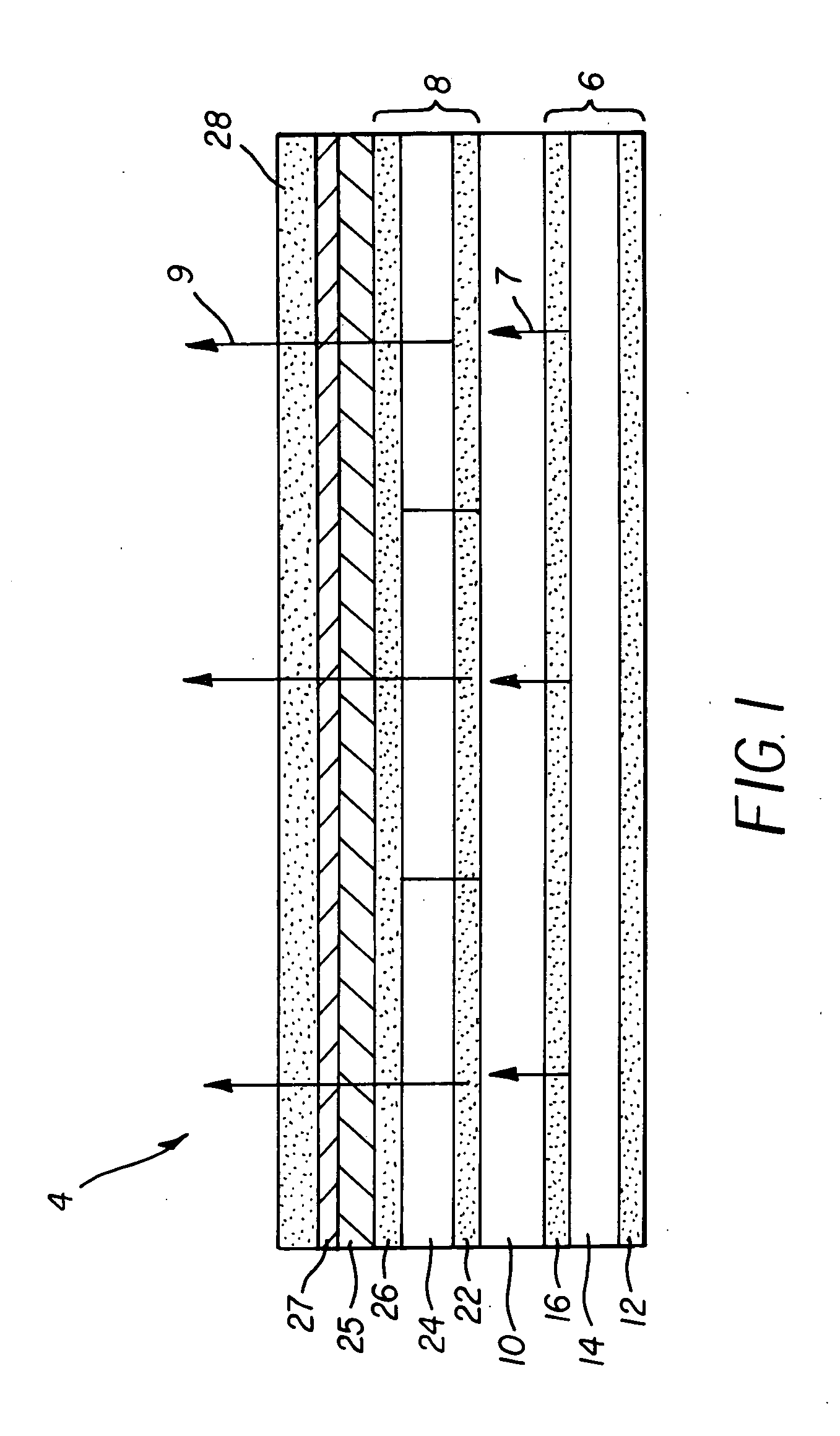
[0020] Referring to FIG. 1, a display 4, according to the present invention, includes a substrate 10 having a first and second side. On a first side, an asymmetric light emitting structure 6 capable of producing polarized light 7 is formed. The asymmetric light emitting structure 6 is used to produce the polarized light 7 that travels through the substrate 10. On the second side of the substrate 10, a transmissive liquid crystal (LC) element 8 is formed having a first liquid crystal electrode 22, a liquid crystal layer 24, and a second liquid crystal electrode 26. The liquid crystal electrodes 22 and 26 provide independently, electrically controlled elements for a pixilated LCD, as is known in the art. The liquid crystal electrodes 22 and 26 can apply an electrical field across the liquid crystal layer 24, so that in one state the liquid crystal layer 24 is transmissive and in another state the liquid crystal layer 24 is not transmissive. Depending on the state of the liquid crystal...


PUM


Abstract

An asymmetric light emitting structure for producing polarized light that includes a light emitting layer having a plurality of light emitting species, wherein orientation of the light emitting species is uncontrolled. Receipt of the emitted light from the light emitting layer is accomplished via an asymmetric geometric element that also produces polarized light. Additionally, the asymmetric light emitting structure includes a means for excitation of the light emitting layer.

Description

FIELD OF THE INVENTION [0001] The present invention relates to organic light emitting devices and, more particularly to the use of organic light emitting devices as backlights in liquid crystal displays. BACKGROUND OF THE INVENTION [0002] Conventional transmissive liquid crystal displays (LCDs) use a white backlight, together with patterned color filter arrays (CFAs), to create colored pixel elements as a means of displaying color. Polarizing films polarize light. The pixels in a conventional liquid crystal display are turned on or off through the use of an additional layer of liquid crystals in combination with two crossed polarizer structures on opposite sides of a layer of polarizing liquid crystals. When placed in an electrical field with a first orientation, the additional liquid crystals do not alter the light polarization. When the electrical field is changed to a second orientation, the additional liquid crystals alter the light polarization. When light from the polarizing l...

Claims


Application Information

Patent Timeline
IPC IPC(8): G02F1/13357H01L27/32H01L33/44H01L51/52H01S5/026H01S5/04H01S5/183H01S5/36H01S5/40H01S5/42
CPCB82Y10/00B82Y20/00G02F1/133603H01L27/32H01L27/3232H01L51/5262H01S5/423H01S5/041H01S5/18302H01S5/18308H01S5/18355H01S5/36H01S5/4087H01L51/5293H10K59/50H10K59/00H10K50/85H10K50/868
Inventor COK, RONALD S.SPOONHOWER, JOHN P.
Owner EASTMAN KODAK CO
Why Eureka
Try Eureka