
Apparatus and method for thermal processing of substrate

Active Publication Date: 2005-03-24
DAINIPPON SCREEN MTG CO LTD
View PDF21 Cites 51 Cited by
  • Summary
  • Abstract
  • Description
  • Claims
  • Application Information

AI Technical Summary

Benefits of technology

[0014] According a preferred embodiment of the present invention, the light entrance portion is disposed on a side of a substrate inside the chamber body, the light emitting part comprises a flash lamp, and the measuring part is a calorimeter. It is thereby possible to measure energy given to the substrate in an extremely short time.

Problems solved by technology

In the thermal processing apparatus using lamps, there is a possibility of reducing light energy which would reach a surface of the substrate due to deterioration of the lamps, stains and dirt on windows of a chamber through which light enters or the like.
The reduction in light energy going into the chamber due to the stains and dirt on the windows of the chamber can not be grasped by monitoring the energy of light going out from the lamps near the lamps.
Since the irradiation time of the flash lamps is extremely short and it is therefore impossible to measure the light energy with high accuracy by a method of using a generally-used photosensor, a method of monitoring infrared rays passing through the substrate, a method of calculating the spectral distribution on a surface of the substrate or the like, it is hard to detect deterioration and a breakdown of the flash lamps due to time variation or the like.
In a case where a processing for a substrate is performed with the energy of light emitted into the chamber lowered, there arises a possibility of causing a failure in the processing for a substrate.
On the other hand, in the thermal processing apparatus using the flash lamps, since heating for a substrate is performed in an extremely short time, it is disadvantageously difficult to measure a surface temperature of a substrate during thermal processing in real time.

Method used


Image

  • Apparatus and method for thermal processing of substrate
  • Apparatus and method for thermal processing of substrate
  • Apparatus and method for thermal processing of substrate

Examples


Embodiment Construction

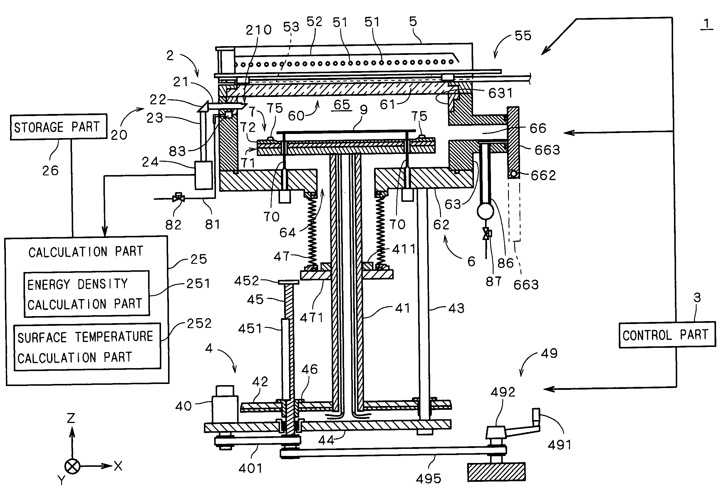
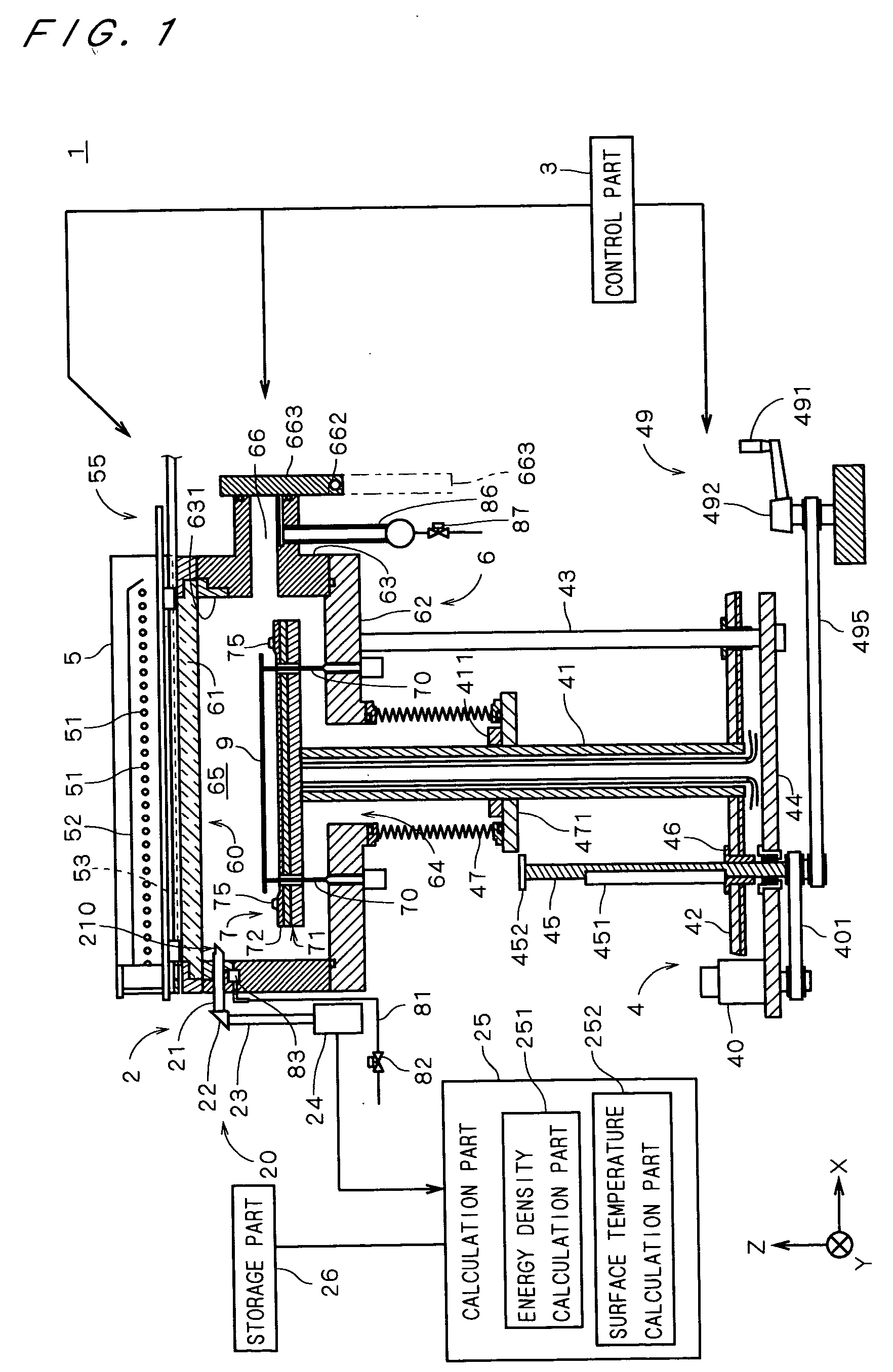
[0031]FIG. 1 is a view showing a construction of a thermal processing apparatus 1 in accordance with the first preferred embodiment of the present invention. The thermal processing apparatus 1 is an apparatus for performing a processing accompanied with heating through irradiating a semiconductor substrate 9 (hereinafter, referred to as “substrate 9”) with light.

[0032] The thermal processing apparatus 1 comprises a chamber side part 63 having a substantially-cylindrical inner wall and a chamber bottom 62 covering a lower portion of the chamber side part 63, which constitute a chamber body 6 forming a space (hereinafter, referred to as “chamber”) 65 in which the substrate 9 is processed and comprising an opening (hereinafter, referred to as “upper opening”) 60 in its upper portion.

[0033] The thermal processing apparatus 1 further comprises a transparent plate 61 which is a closing member attached to the upper opening 60 for closing the upper opening 60, a substantially disk-shaped ...


PUM

PropertyMeasurementUnit
Temperatureaaaaaaaaaa
Energyaaaaaaaaaa
Lightaaaaaaaaaa

Abstract

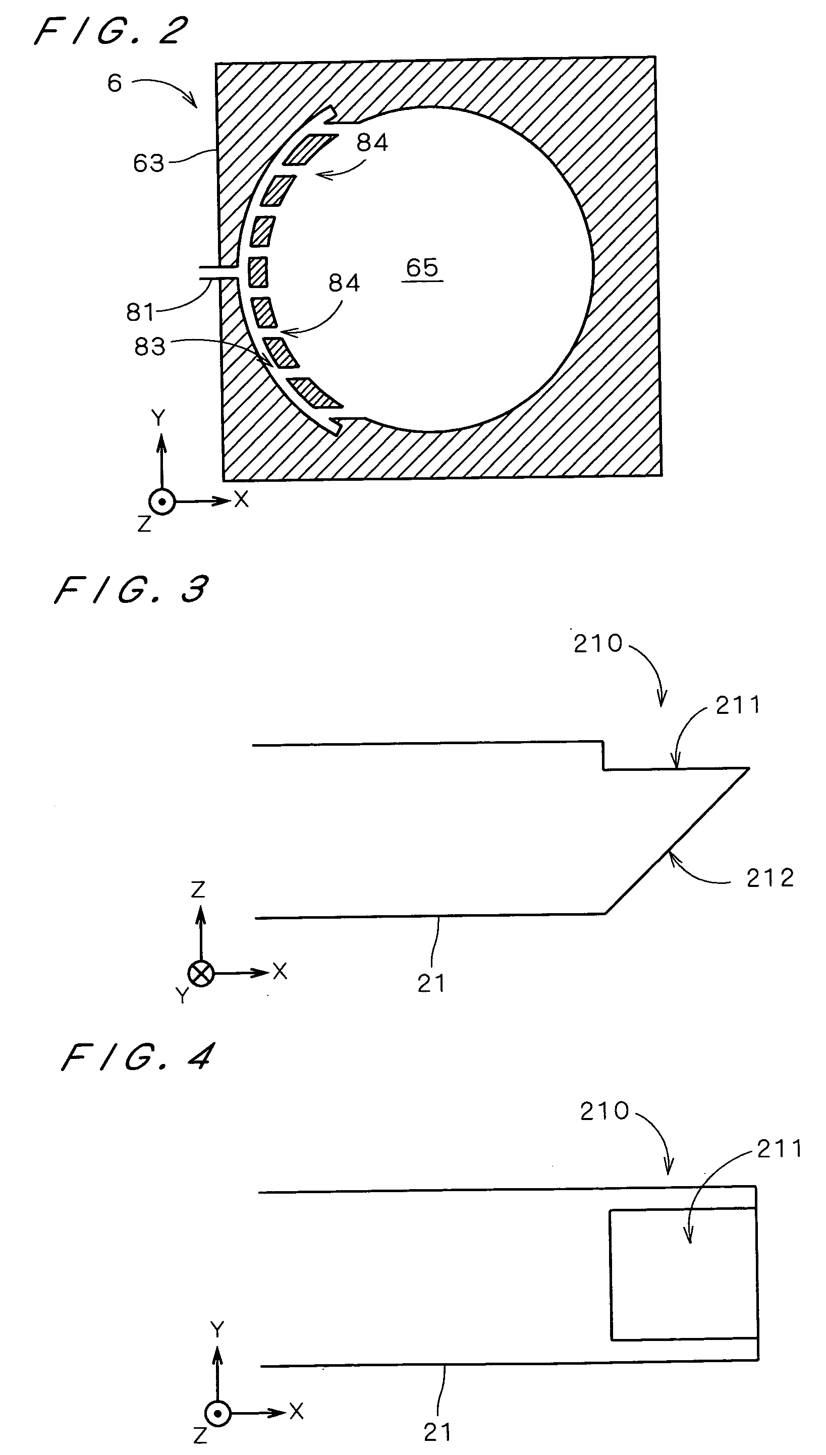
A thermal processing apparatus (1) comprises a chamber body (6), a holding part (7) for holding a substrate (9) inside the chamber body (6), a light emitting part (5) for heating the substrate (9) through light irradiation and a light measuring part (2) for measuring light energy. The light measuring part (2) comprises a calorimeter (24) disposed outside the chamber body (6), a light guide structure (20) for guiding the light inside the chamber body (6) to the calorimeter (24) and a calculation part (25) for performing computations on the basis of an output of the calorimeter (24). In the thermal processing apparatus (1), by measuring the light from the light emitting part (5) by the calorimeter (24), it is possible to measure the energy of light emitted from the light emitting part (5) during thermal processing inside chamber body (6) and obtain a surface temperature of the substrate (9) by the calculation part (25).

Description

BACKGROUND OF THE INVENTION [0001] 1. Field of the Invention [0002] The present invention relates to a technique for performing a processing accompanied with heating on a substrate. [0003] 2. Description of the Background Art [0004] Conventionally, in various stages of a process for manufacturing a semiconductor substrate, a glass substrate for a display device or the like (hereinafter, referred to simply as “a substrate”), a thermal processing is performed for the substrate, and a rapid thermal process (hereinafter, referred to as “RTP”) is used as a method of thermal processing. In the RTP, by heating the substrate in a chamber with halogen lamps or the like to raise the temperature thereof up to a predetermined temperature in a short time, it is possible to perform processings which have been hard to execute by a conventional long thermal processing with an electric furnace, such as thinning of an insulating film such as an oxide film, suppressing of rediffusion of impurities (or...

Claims


Application Information

Patent Timeline
IPC IPC(8): H01L21/00H01L21/26H01L21/31C23C16/46
CPCH01L21/67115
Inventor KUSUDA, TATSUFUMI
Owner DAINIPPON SCREEN MTG CO LTD
Learn More