Transition duct honeycomb seal

Active Publication Date: 2005-03-24
H2 IP UK LTD
View PDF7 Cites 23 Cited by
  • Summary
  • Abstract
  • Description
  • Claims
  • Application Information

AI Technical Summary

Benefits of technology

[0006] A sealing device for use between a gas turbine combustor transition duct aft frame and a turbine inlet having improved durability, reduced wear on the mating turbine vane, and reduced manufacturing costs, is disclosed. The sealing device comprises a first end and second end in spaced relation forming a circumferential length, a forward face and an aft face in spaced relation forming an axial width, and an inner surface and an outer surface in spaced relation forming a radial height. A plurality of channels extends axially along the inner surface for passing a known amount of cooling air to cool the turbine vane platform. The sealing device is formed of abradable honeycomb having a plurality of honeycomb cells, with each cell having a wall thickness and cell width. The honeycomb cells are oriented generally perpendicular to the transition duct aft frame to ensure maximum control against cooling air leakage while also providing maximum flexibility during assembly. A nomi

Problems solved by technology

Since the sealing device is fabricated from a softer material than the turbine vane platform and the vane platform will move into the sealing device due to relative thermal expansion during operation, some initial wear will occur to the sealing devi

Method used


Image

  • Transition duct honeycomb seal
  • Transition duct honeycomb seal
  • Transition duct honeycomb seal

Examples


Embodiment Construction

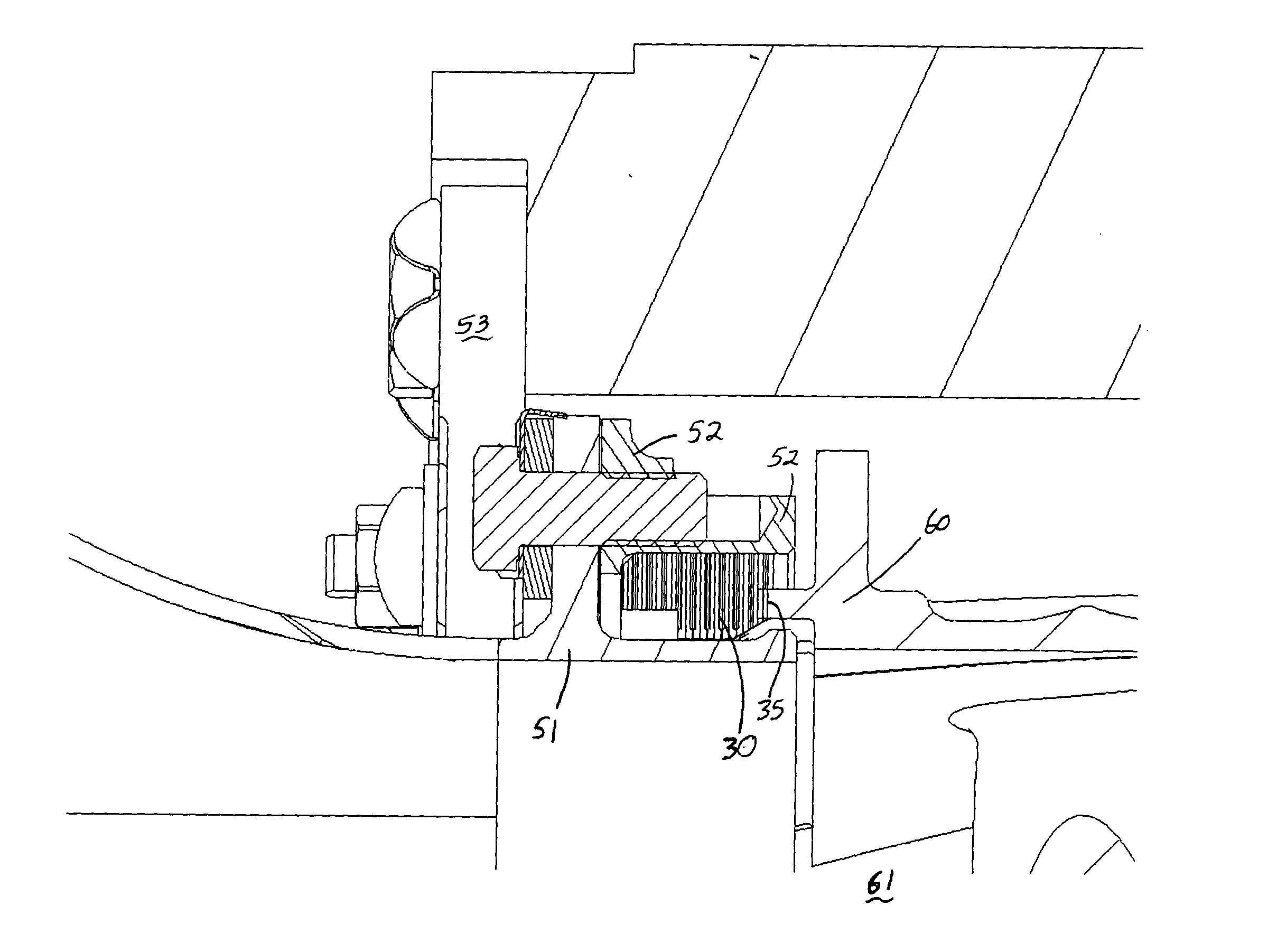
[0019] The preferred embodiment of the present invention is shown in detail in FIGS. 3-6 and installed on a gas turbine combustor transition duct in FIGS. 7 and 8. The sealing device is preferably designed for use between a gas turbine combustor transition duct aft frame and a turbine inlet region. Referring now to FIG. 3, sealing device 30 is shown in plane view and comprises a first end 31 and a second end 32 in spaced relation thereby forming a circumferential length 33. FIG. 5 shows an end view of sealing device 30 that depicts a forward face 34 and an aft face 35 in spaced relation thereby forming an axial width 36. Furthermore, sealing device 30 has an inner surface 37 and an outer surface 38 in spaced relation thereby forming a radial height 39.

[0020] Referring back to FIG. 4, a portion of sealing device 30 is shown in greater detail. A plurality of channels 40 is shown extending axially along inner surface 37. Each of channels 40 has a channel width 41 and a channel depth 4...


PUM


Abstract

A sealing device for use between a gas turbine combustor transition duct aft frame and a turbine inlet having improved durability, reduced wear on the mating turbine vane, and reduced manufacturing costs, is disclosed. The sealing device has a circumferential length, an axial width, and a radial height and contains a plurality of channels extending axially along the seal inner surface for passing a controlled amount of cooling air to a turbine inlet. The sealing device is formed of abradable honeycomb having a plurality of honeycomb cells with the honeycomb cells oriented to ensure maximum control against cooling air leakage while also providing maximum flexibility during assembly. The sealing device is captured between the transition duct aft frame, bulkhead, and turbine vane platform, thereby allowing easy replacement of the seal without requiring major disassembly of the transition duct aft frame section.

Description

TECHNICAL FIELD [0001] This invention applies to the combustor section of gas turbine engines used in powerplants to generate electricity. More specifically, this invention relates to the sealing structure between a transition duct and the inlet of a turbine. BACKGROUND OF THE INVENTION [0002] In a typical can-annular gas turbine engine, a plurality of combustors are arranged in an annular array about the engine. The combustors receive pressurized air from the engine's compressor, add fuel to create a fuel / air mixture, and combust that mixture to produce hot gases. The hot gases exiting the combustors are utilized to turn a turbine, which is coupled to a shaft that drives a generator for generating electricity. [0003] In a typical gas turbine engine, transition ducts are surrounded by a plenum of compressed air from the engine's compressor. This air is directed to the combustors and also cools the transition duct walls. Due to the pressure loss associated with the combustion process...

Claims


Application Information

Patent Timeline
IPC IPC(8): F01D9/02F01D11/00
CPCF01D11/003F01D9/023
Inventor JORGENSEN, STEPHEN W.
Owner H2 IP UK LTD
Why Eureka
Try Eureka