Rotating member and method for coating the same

a technology of rotating parts and electrodes, which is applied in the direction of wind turbine components, non-positive displacement fluid engines, liquid fuel engine components, etc., can solve the problems of many pretreatments, high cost, and gas turbine troubles, and achieve the effect of reducing the amount of electrode materials for coating and sufficient abrasive properties

Inactive Publication Date: 2005-03-24
MITSUBISHI ELECTRIC CORP +1
View PDF29 Cites 28 Cited by
  • Summary
  • Abstract
  • Description
  • Claims
  • Application Information

AI Technical Summary

Benefits of technology

Furthermore, a second object of the present invention is to provide a rotating member in which an area of coating of a hard material can be optimized to enhance a yield and a method for coating the rotating member.
In a 30th invention, there is provided the method of manufacturing the rotating member, wherein the ratio of the coverage is controlled to provide the rotating member which does not easily collapse from fatigue.

Problems solved by technology

Conversely, when the clearance is set to be excessively small, a tip end of the rotating member breaks and causes a trouble of the gas turbine.
However, in the above-described methods, a portion which does not have to be coated is masked in order to closely attach the abrasive coating, the surface to be coated needs to be blast-treated in order to enhance adhesion, and there are problems that there are many pretreatments and costs are high.
In either conventional thermal spraying or plating method, there have been problems that the adhesion of the coating is bad, peel occurs at the time of the driving, an engine trouble is caused, and additionally the chip clearance or the seal clearance is not kept to be appropriate.
Furthermore, there has been a problem that with the coating by the welding, only a metal much lower in hardness can be coated as compared with a ceramic, and therefore abrasive properties (properties for chipping off a material to be ground) are inferior.
Moreover, there has been a problem that a quality level fluctuates by an operator's expertise, and a welding crack easily occurs with respect to a material bad in thermal conductivity and small in elongation.
Furthermore, there has been a problem that post-treatments such as grinding for processing to a required dimension after the welding are required, and a lot of trouble is required.
Moreover, in the conventional abrasive coating, since the whole area of the tip end of the blade is coated, there has been a problem that a coating range is broad and yield of products is bad.
Therefore, an operation time required for the production (manufacturing) of the labyrinth seal lengthens, and it is not easy to enhance productivity of the labyrinth seal.
Additionally, for the same reason, the abrasive coat cannot firmly be attached to the tip edge of a seal fin.
Therefore, there has been a problem that the abrasive coat easily peels off the tip edge of the seal fin and the quality level of the labyrinth seal is not stable.

Method used


Image

  • Rotating member and method for coating the same
  • Rotating member and method for coating the same
  • Rotating member and method for coating the same

Examples


first embodiment

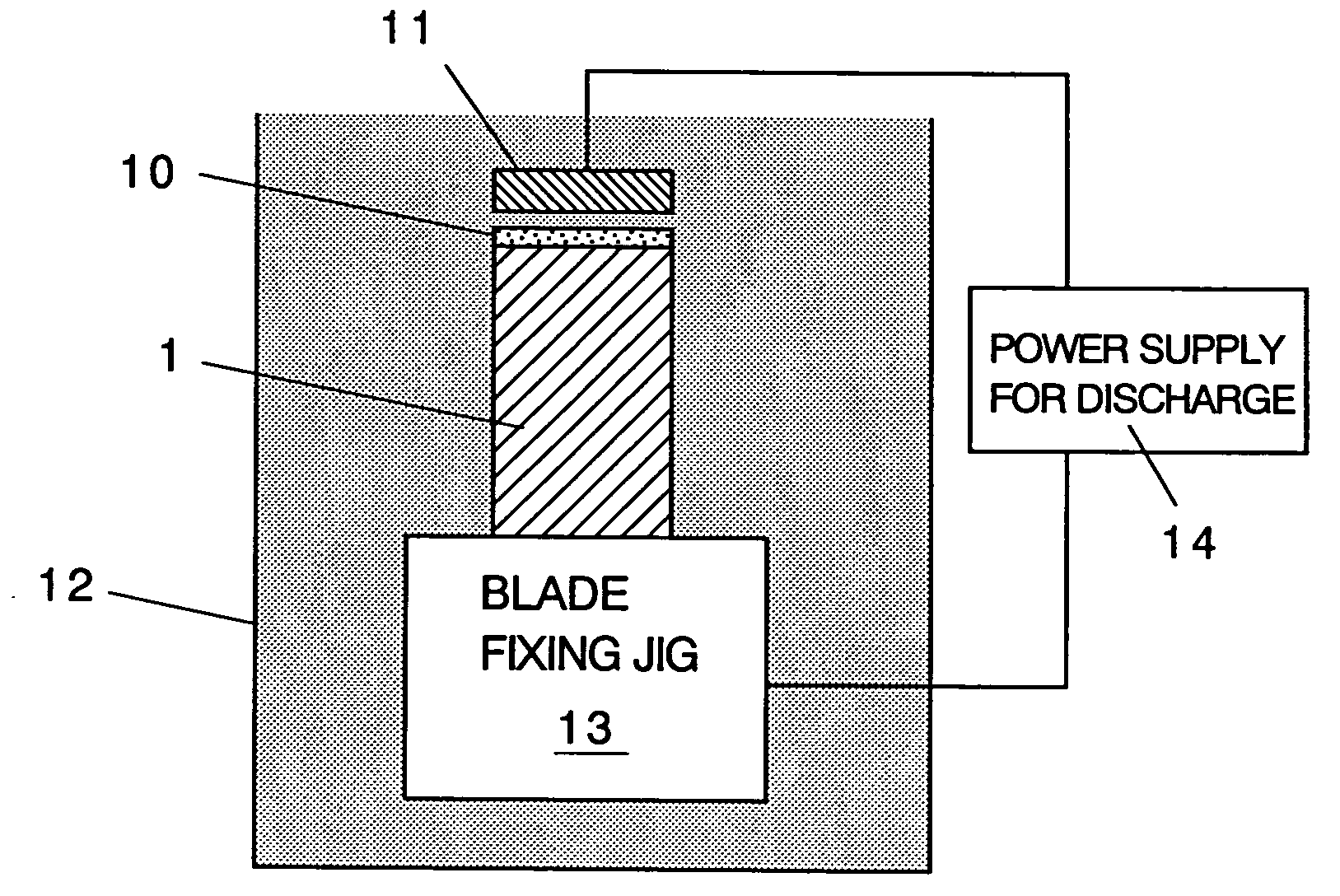
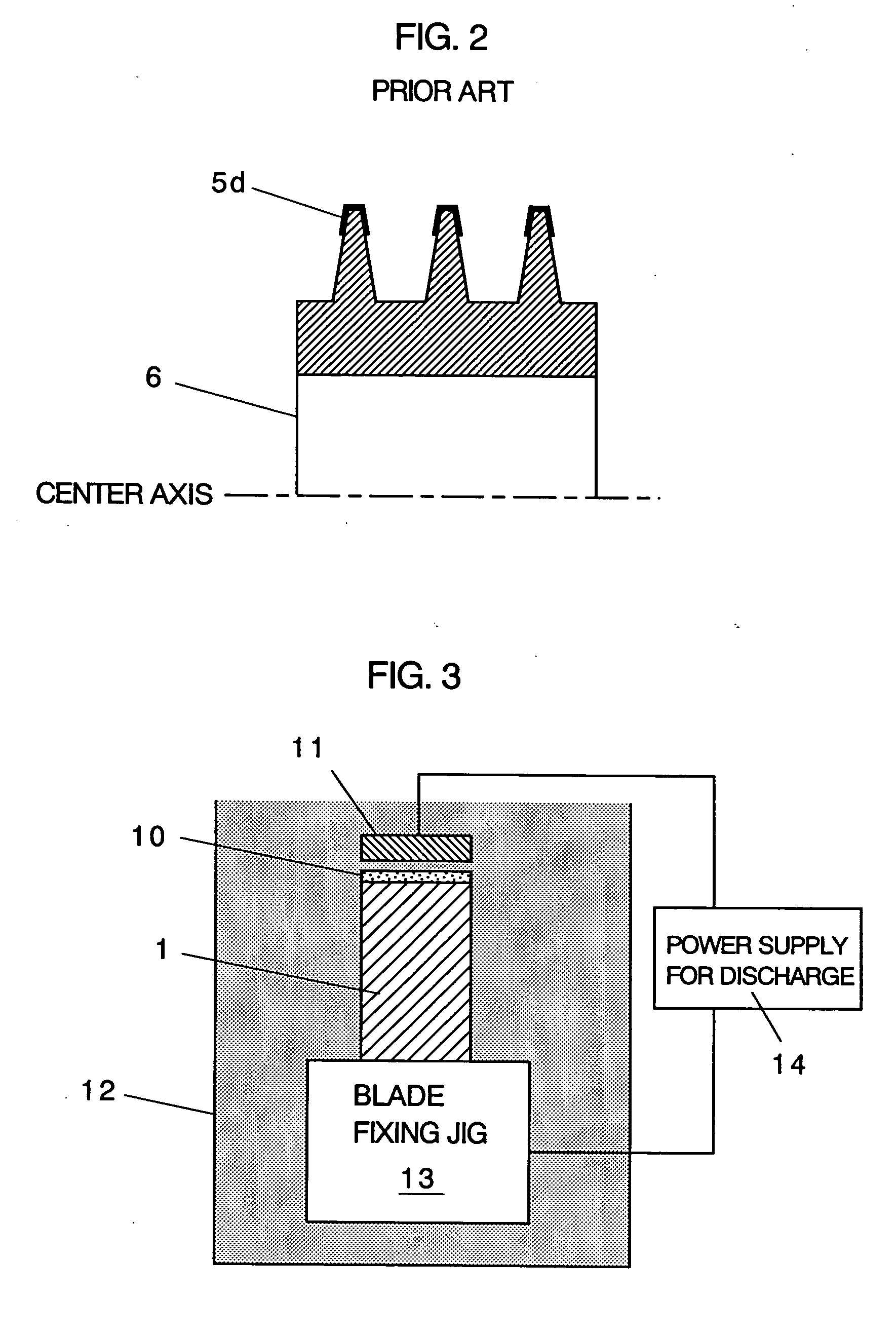
FIG. 3 is a diagram showing a rotating member and coating method of the present invention. This figure shows that a tip end of a blade 1 for use in a gas turbine or a compressor is coated with a hard material.

In the method of the present invention, as shown in FIG. 3, the blade 1 and a discharge electrode 11 including cubic boron nitride (cBN) is submerged in a processing tank 12 filled with dielectric liquid (oil). A pulsed discharge is caused between the tip end of the blade 1 and the discharge electrode 11 by a power supply for discharge 14 to melt the discharge electrode 11. A part of the electrode is welded to the tip end of the blade 1 to form a cBN-containing coating film 10. Here, only sections of the blade 1 and discharge electrode 11 are shown, the blade 1 is fixed by a blade fixing jig, and the discharge electrode 11 is fixed by an electrode fixing jig (not shown). It is to be noted that FIG. 3 shows an example of the blade, but a labyrinth seal which is the same rotatin...

fifth embodiment

FIG. 10 is a diagram showing the coating method according to the present invention, and is a diagram showing the coating method of the blades shown in FIGS. 7A to 7C. In the coating method of the present invention, the blade 1 and a discharge electrode 23 is submerged in the processing tank 12 filled with the dielectric liquid (oil), the discharge electrode 23 is disposed in the vicinity of the corner in the rotation advance direction of the blade 1, the discharge is caused between them, and only the corner of the blade 1 in the rotation advance direction is coated with the coating 20 of the hard material.

The coating 20 of the hard material is formed to have a very thin thickness of 10 to 20 μm (exaggerated for ease of seeing in the figure). Therefore, after molding the blade 1 as usual, it is sufficient to apply the coating 20 of the hard material only to a range of contact with the opposite member, that is, only the corner of the rotation advance direction or the surface of the r...


PUM

PropertyMeasurementUnit
currentaaaaaaaaaa
currentaaaaaaaaaa
Vickers hardnessaaaaaaaaaa

Abstract

A pulsed discharge is generated between tip ends of a rotating member such as a blade and a discharge electrode including a hard material such as cBN in dielectric liquid or gas by a power supply for discharge to melt the discharge electrode, and a part of the discharge electrode is attached to the tip end of the rotating member to form an abrasive coating film including the hard materials such as cBN.

Description

BACKGROUND OF THE INVENTION 1. Technical Field of the Invention The present invention relates to a rotating member such as a blade or labyrinth seal for use in a gas turbine, steam turbine, compressor or the like, and a method for coating the rotating-member. More particularly, it relates to a rotating member on a part of which a coating film including a hard material is formed, and a method for coating the rotating member. 2. Description of the Related Art For a rotating member such as a blade or a labyrinth seal, a clearance between a rotating section and a stationary section such as a chip clearance between the blade and a casing or a shroud, or a seal clearance between the labyrinth seal and a honeycomb seal needs to be kept / set to be appropriate during operation of a gas turbine. When the clearance is set to be excessively large fearing for contact, an efficiency of the gas turbine drops. Conversely, when the clearance is set to be excessively small, a tip end of the rotati...

Claims


Application Information

Patent Timeline
Patent Type & Authority Applications(United States)
IPC IPC(8): C23C26/00C23C26/02
CPCC23C26/00C23C26/02Y02T50/671F01D11/122Y02T50/67F01D5/288Y02T50/60
Inventor OCHIAI, HIROYUKIWATANABE, MITSUTOSHIARAI, MIKIYASABURI, SHIGERUYAMAKAWA, TSUYOSHITSUGUMI, SHOGOSAKAI, JUNTEZUKA, TSUNAOGOTO, AKIHIROAKIYOSHI, MASAO
Owner MITSUBISHI ELECTRIC CORP
Why Eureka
Try Eureka