Gerotor pumps and methods of manufacture therefor

a gerotor pump and rotor shaft technology, applied in the direction of rotary/oscillating piston pump components, machines/engines, liquid fuel engines, etc., can solve the problem of difficult to form and maintain proper clearance values between the gerotor set and the first and second sides of the gerotor cavity of a gerotor pump configured for high, and the clearance is simply too large for efficient utilization of pumps generating pressure values above a few hundred pounds per square inch

Inactive Publication Date: 2005-03-24
PHILLIPS EDWARD H
View PDF13 Cites 31 Cited by
  • Summary
  • Abstract
  • Description
  • Claims
  • Application Information

AI Technical Summary

Benefits of technology

In another aspect, the present invention is directed to a third improved method for supporting a gerotor set comprised in a gerotor pump, wherein the method comprises the steps of locating the inner rotor of a gerotor set between first and second pressure balancing plates, locating the outer rotor of the gerotor set within a floating ring, locating the floating ring between the first and second pressure balancing plates and laterally with reference to the inner rotor whereby an indep

Problems solved by technology

Because the axes of rotation of the gerotor pump and prime mover drive shafts are each fixedly located, the rotational axis of the gerotor pump shaft cannot in general be truly co-axial with the prime mover drive shaft.
In addition, such gerotor pumps are generally provided with a shaft seal in order to retain the fluid within the pump itself thus tending to make a long and rather complex assembly of the resulting prime mover/coupling/gerotor pump assembly.
In addition to all of the above, it is difficult to form and maintain proper clearance values between the gerotor set and the first and second sides of the gerotor cavity of a gerotor pump configured for high pressure system loads (i.e., as determined by the difference in gerotor set thickness and effective center plate thickness).
T

Method used


Image

  • Gerotor pumps and methods of manufacture therefor
  • Gerotor pumps and methods of manufacture therefor
  • Gerotor pumps and methods of manufacture therefor

Examples


seventh embodiment

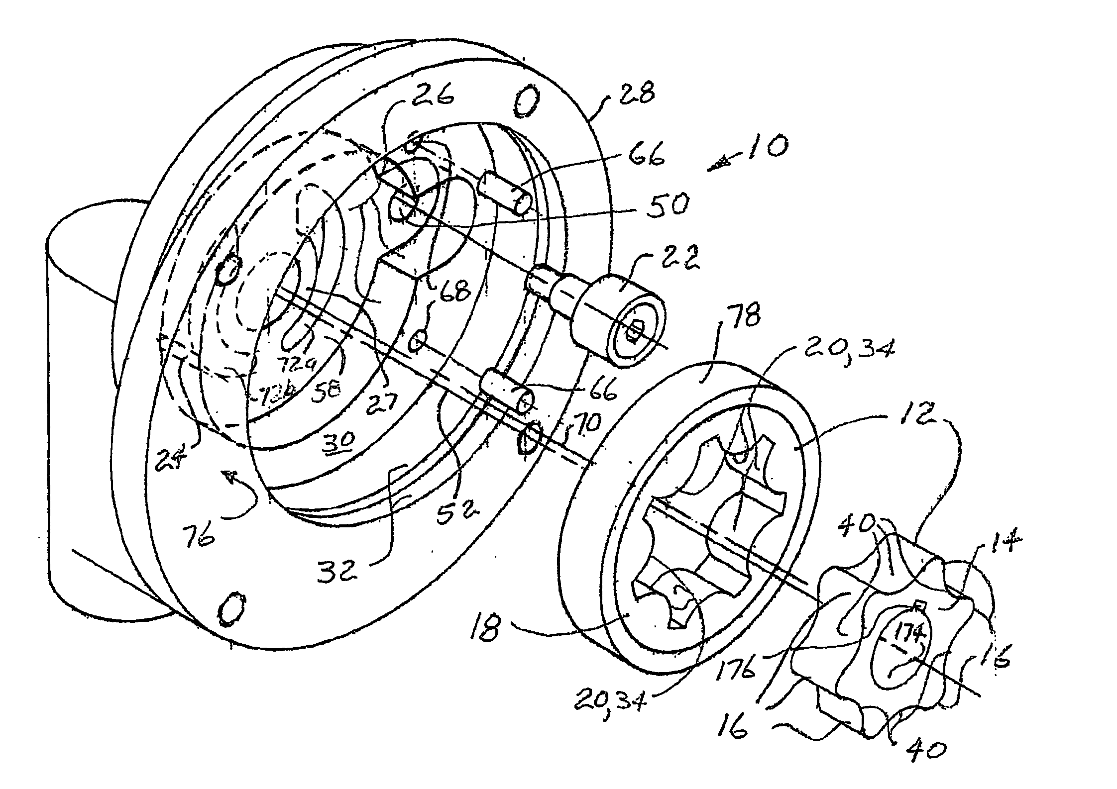
A third improved method of supporting gerotor sets comprised in gerotor pumps has been additionally enabled by the present invention. As depicted in FIG. 31, this method comprises the steps of locating the inner rotor of a gerotor set between first and second pressure balancing plates; locating the outer rotor of the gerotor set within a floating ring; locating the floating ring between the first and second pressure balancing plates and laterally with reference to the inner rotor whereby an independent pumping cartridge comprising the gerotor set, floating ring, and the first and second pressure balancing plates is formed; rotationally driving the inner rotor via rotationally driving engagement of the inner rotor with a drive shaft;

providing a rotational constraint for the independent pumping cartridge, allowing the outer rotor located within the floating ring to find its own eccentricity offset rotation axis location with reference to the axis of rotation of the inner rotor via me...


PUM


Abstract

Improved gerotor pumps (10, 100, 150, 180, 210, 230, 260, 270, 310, 340, 370, 400) each featuring an outer rotor (18, 184, 202) of a gerotor set (12, 186, 204, 344) located laterally with respect to a preferred eccentricity axis (54), but allowed to float in the orthogonal direction nominally along the preferred eccentricity axis and find its own eccentricity offset rotation axis (5440 ) via mesh of the gerotor set itself are provided in the present invention. Reduced gerotor set operating clearances for the gerotor sets, and therefore higher attained output pressure values, are attained by utilization of any of methods also presented for reforming tip regions of either or both of the inner and outer rotors.

Description

BACKGROUND OF THE INVENTION I. Field of the Invention The present invention relates generally to gerotor pumps, and more particularly to improved gerotor pumps wherein outer rotors are enabled for finding their own eccentricity offset axes, and furthermore, to improved methods of manufacture for preferred gerotor gear sets to be utilized therein. II. Description of the Prior Art Gerotor pumps are most conveniently designed around commercially available gerotor gear sets (hereinafter simply “gerotor sets”) such as those manufactured by Nichols Portland of Portland, Me. Such gerotor sets comprise an inner rotor having N outwardly extending lobes with N approximately circularly shaped grooves therebetween (i.e., with N typically having values of 4, 6, 8 or 10) in mesh with an eccentrically disposed outer rotor comprising N+1 inwardly extending circularly shaped elements. Generally, the inner rotor is mounted upon and driven by a shaft drivingly coupled to the drive shaft of a prime...

Claims


Application Information

Patent Timeline
IPC IPC(8): F04C2/08F04C2/10F04C14/22F04C15/00
CPCF04C2/084F04C2/086F04C2/102F04C14/226F04C2240/52F04C15/0073F04C2230/00F04C2230/602F04C2240/51F04C15/0019
Inventor PHILLIPS, EDWARD H
Owner PHILLIPS EDWARD H
Why Eureka
Try Eureka