
Material reservation distribution system and method

a distribution system and material technology, applied in the field of industrial control systems, can solve the problems of complex factory equipment arrangement and programming, inflexible programming models, inefficient and costly in asset utilization and material control, and complex programming models, etc., to achieve efficient management, facilitate material-based processing, and mitigate waste

Inactive Publication Date: 2005-03-24
ROCKWELL AUTOMATION TECH
View PDF10 Cites 49 Cited by
  • Summary
  • Abstract
  • Description
  • Claims
  • Application Information

AI Technical Summary

Benefits of technology

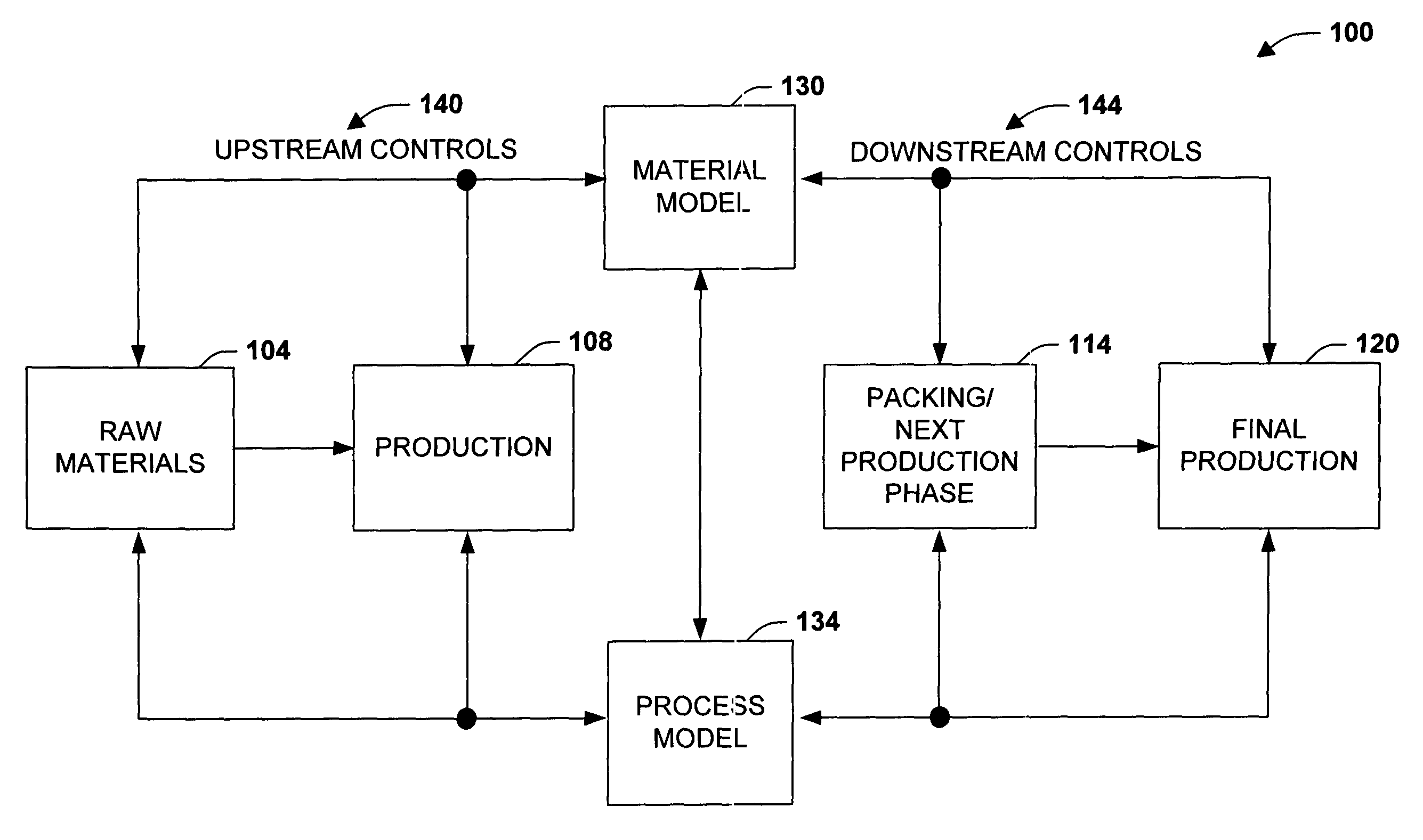
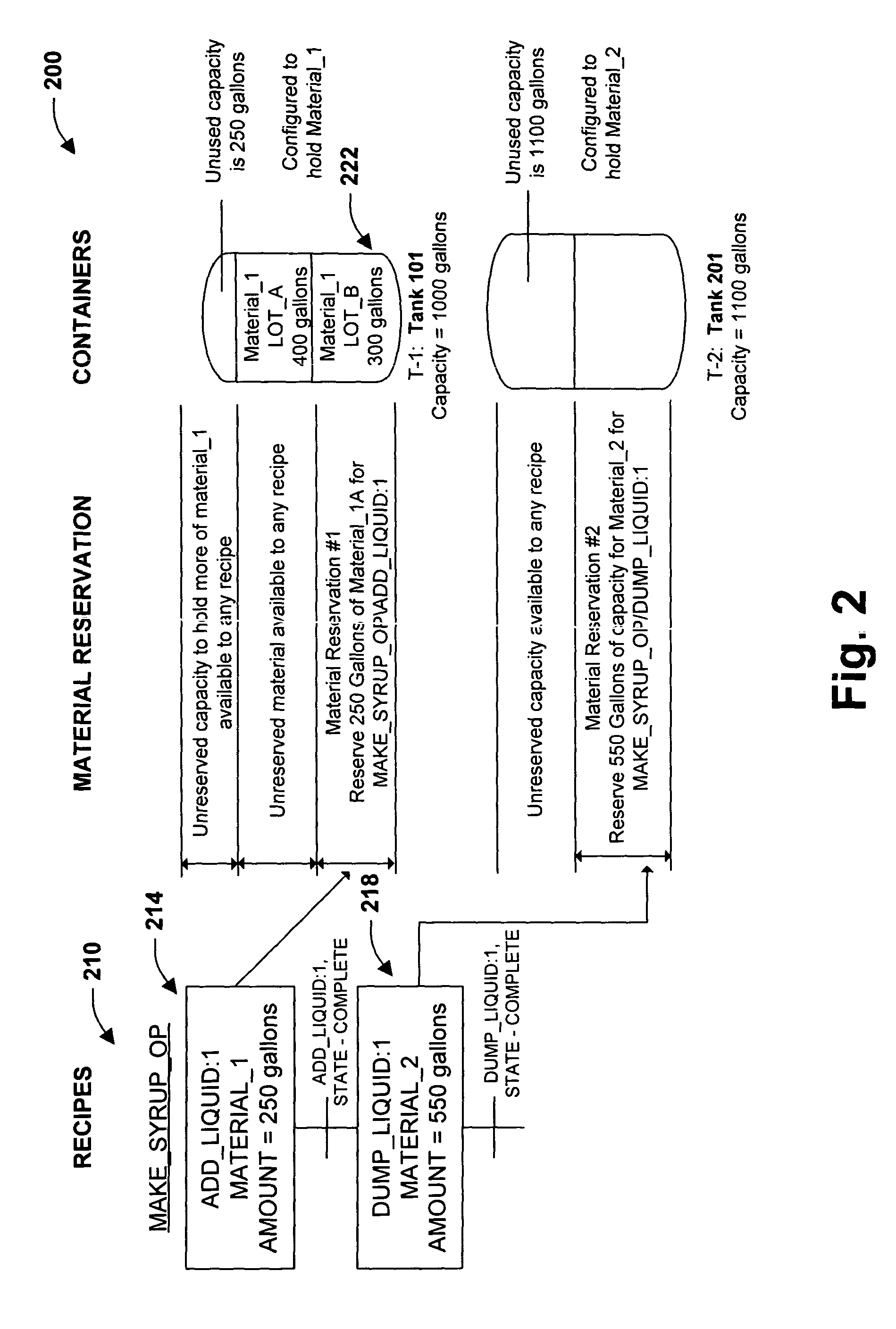
[0007] The present invention relates to a system and methodology to facilitate material-based processing in an industrial automation environment. Inventory is dynamically managed by controlling relationships between material inventory reservation requirements and unused equipment capacity. These relationships are controlled within a context or framework that automatically determines and selects equipment to be employed before and / or during a running batch process. As recipes are executed, material requirements and potential equipment for processing the materials are determined. Rather than allocating and distributing materials to and from predetermined containers and vessels, the present invention employs a materials-based mapping to dynamically control and select available assets to perform desired recipe operations. Thus, in one example, as recipe steps are executed, a recipe material may be directed to / from a plurality of available sources that may alternatively supply / receive the recipe material based upon material reservation requirements specified in the recipe. Similarly, materials can be distributed based upon alternative sources of available capacity for receiving material distributions. In this manner, materials can be more efficiently managed from a plurality of dynamically selected options while mitigating waste that may arise from conventional systems that do not support dynamic capacity allocations and material mapping.
[0009] Based upon material attributes, respective equipment can be selected in accordance with asset availability and / or asset capability in a more efficient manner. For example, if a conventional Process A were narrowly defined as being stored by containers 1, 2, and 3, and being made by associated equipment X and Y, then only those respective components could be employed to replicate the process—without reprogramming the process even though other resources may be available for manufacturing Process A (e.g., a portion of a tank or vessel cable of holding or disposing similar materials). In contrast, if Process B were defined in terms of materials, and provided with a material-to-process mapping in accordance with the present invention, then the process can be dynamically implemented in accordance with any available storage / processing containers having desired materials, material processing capabilities, and having access to available or alternative equipment resources. In this manner, materials can be more efficiently stored / allocated by tracking to an inventory model during process operations that includes upstream and / or downstream inventory controls (e.g., material model notifies raw inventory database upstream when process components have been depleted, material model notifies downstream process of an intermediate batch mixture that can be potentially employed in another process).

Problems solved by technology

Often, complex factory equipment arrangements and programming are provided to produce all or portions of such products.
This type of programming model, however, can be inflexible, inefficient and costly in terms of asset utilization and in terms of material controls.
It becomes even more complicated if there is more than one storage container for each material.
Therefore, equipment-based programming models typically lead to less than efficient asset utilization and generally lead to increased inventory costs.

Method used


Image

  • Material reservation distribution system and method
  • Material reservation distribution system and method
  • Material reservation distribution system and method

Examples


example

[0097] MBR_ADD:1 requires an addition of Material—1, Lot—5.

[0098] MBR_ADD:2 requires an addition of Material—3, Lot—4.

[0099] MBR_DUMP:1 requires a distribution of Material—6, Lot—1, Label—2.

[0100] In this example, Unit 1 is selected because it can draw the materials with the specified lots. The lot and label for MBR_DUMP:1 are ignored until the material is distributed to Container—7. The lot and label are then assigned to the material

[0101]FIG. 13 illustrates a material driven methodology in accordance with an aspect the present invention. While, for purposes of simplicity of explanation, the methodology is shown and described as a series of acts, it is to be understood and appreciated that the present invention is not limited by the order of acts, as some acts may, in accordance with the present invention, occur in different orders and / or concurrently with other acts from that shown and described herein. For example, those skilled in the art will understand and appreciate that ...


PUM


Abstract

The present invention relates to a system and methodology facilitating material-driven processing in an industrial controller environment. Various models supported by database objects are provided to automatically and dynamically map inventory systems / processes to control systems / process such as in batch or recipe operations. A material model is provided that tracks to an inventory database and includes such aspects as defining material types and containers to house such materials. An area model maps the material model to possible units and equipment modules to process the materials. These models include phased-based parameters that define amounts of material that flow into and out of a determined area for processing the materials. Before, during and / or after automated manufacturing operations, object binding operations occur between material-based servers associated with an inventory system and batch servers associated with a process-control system. Such binding includes Just-In-Time or on-demand binding at run time, and relates material requirements of a recipe (or batch) to the units and equipment that are available to produce the recipe.

Description

TECHNICAL FIELD [0001] The present invention relates generally to industrial control systems, and more particularly to a system and methodology to facilitate material-driven processing in an automated industrial controller environment. BACKGROUND OF THE INVENTION [0002] Industrial controllers are special-purpose computers utilized for controlling industrial processes, manufacturing equipment, and other factory automation, such as data collection or networked systems. In accordance with a control program, the industrial controller, having an associated processor (or processors), measures one or more process variables or inputs reflecting the status of a controlled system, and changes outputs effecting control of such system. The inputs and outputs may be binary, (e.g., on or off), as well as analog inputs and outputs assuming a continuous range of values. [0003] Measured inputs received from such systems and the outputs transmitted by the systems generally pass through one or more in...

Claims


Application Information

Patent Timeline
Patent Type & Authority Applications(United States)
IPC IPC(8): G06Q10/00
CPCG05B2219/31386G06Q20/203G06Q10/00G05B2219/31388
Inventor KAPPELHOFF, RALPH L.D'MURA, PAUL R.
Owner ROCKWELL AUTOMATION TECH
Learn More